3D printing equipment with multiple feeding tubes

A 3D printing, multi-feeding technology, applied in the field of 3D printing, can solve the problems of high drive device matching requirements, print head vibration, cumbersome printing process, impact on printing quality, etc., to avoid clogging, improve smoothness, and reduce vibration.

Inactive Publication Date: 2015-12-09
WUHU SIRUIDI THREE DIMENSIONAL TECH CO LTD
View PDF5 Cites 17 Cited by
  • Summary
  • Abstract
  • Description
  • Claims
  • Application Information

AI Technical Summary

Problems solved by technology

[0003] The current 3D printing equipment is driven in a variety of ways. Existing 3D printing equipment usually includes horizontal tracks. The horizontal tracks include X tracks and Y tracks that are perpendicular to each other. 3D printing equipment uses multiple driving devices to drive the printing head to move in the horizontal and vertical directions to achieve printing. This method of movement requires high coordination between the various driving devices and it is difficult to avoid vibration of the printing head, which affects the printing quality. If the consumables are missing during the printing process of the existing 3D printing equipment, the operation of the 3D printing equipment needs to be stopped, and the printing will continue after the replacement of the consumables is completed, and the printing process of the current 3D printing equipment is quite cumbersome if it prints color products

Method used


Image

  • 3D printing equipment with multiple feeding tubes
  • 3D printing equipment with multiple feeding tubes

Examples


Embodiment Construction

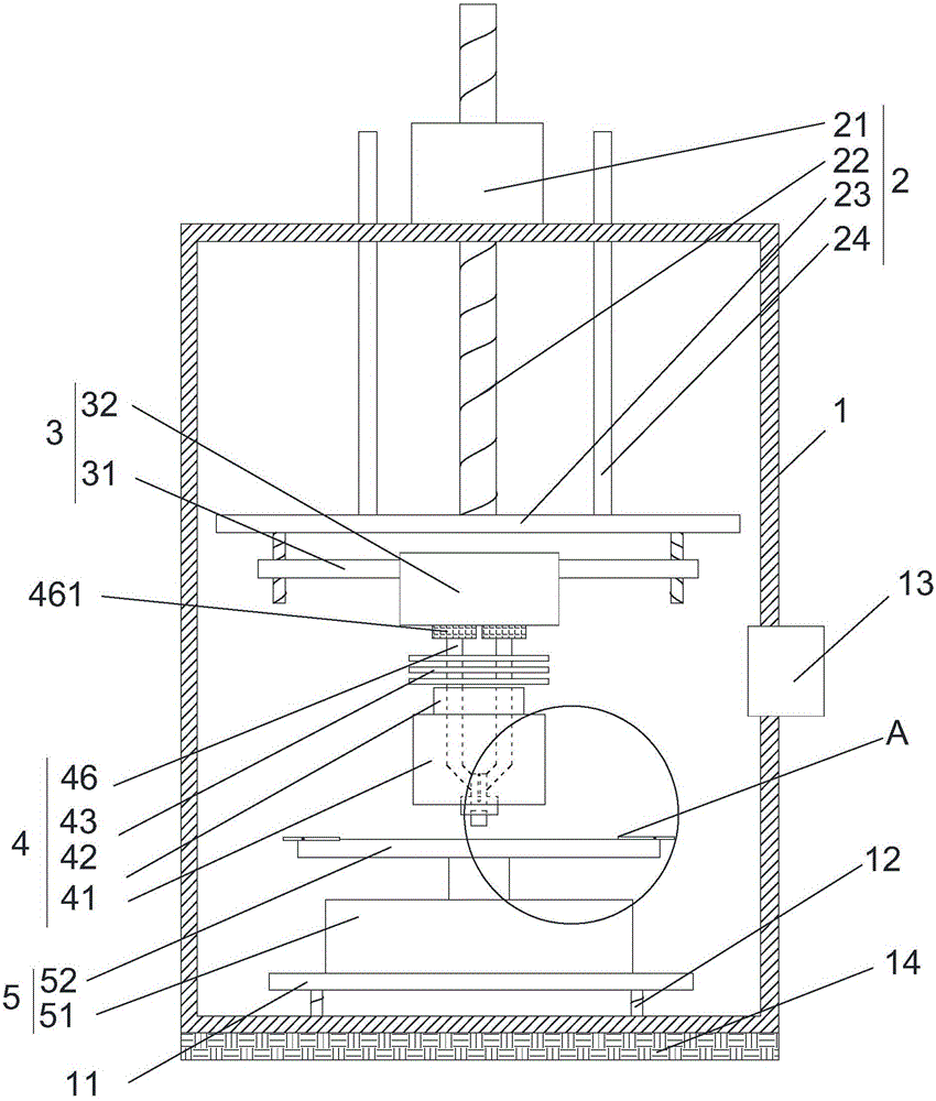
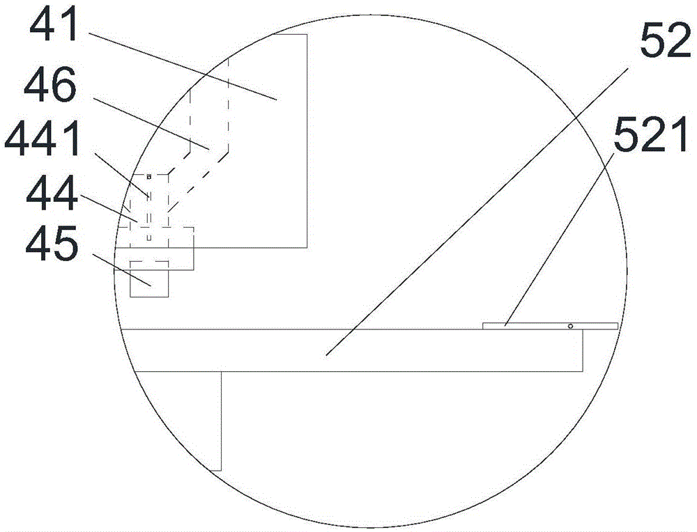
[0018] refer to figure 1 and figure 2 As shown, a multi-feed tube 3D printing device proposed by the present invention includes a mounting frame 1, a vertical movement mechanism 2, a horizontal movement mechanism 3, a print head 4 and a printing support mechanism 5;

[0019] The vertical movement mechanism 2 includes a first driving device 21, a lifting rod 22, a mounting plate 23 and a positioning rod 24. The first driving device 21 is installed on the mounting frame 1, and the first driving device 21 is driven to connect the lifting rod 22. The first driving device The device 21 drives the lifting rod 22 to lift, the mounting plate 23 is installed on the lower end of the lifting rod 22, the lower end of the positioning rod 24 is installed on the mounting plate 23, and the upper end of the positioning rod 24 passes through the mounting frame 1;

[0020] The horizontal movement mechanism 3 includes a horizontal movement rod 31 and a second drive mechanism 32, the horizontal ...


PUM


Abstract

The invention discloses 3D printing equipment with multiple feeding tubes. The 3D printing equipment comprises a mounting rack, a vertical moving mechanism, a horizontal moving mechanism, a printing head and a printing supporting mechanism, wherein the vertical moving mechanism comprises a first drive device, a lifting rod, a mounting plate and a positioning rod; the horizontal moving mechanism comprises a horizontal moving rod and a second drive mechanism; the printing head comprises a plurality of heating devices, a heat insulating device, a radiating device, a spray head, a spray nozzle and a plurality of feeding tubes; the heat insulating device is mounted above the heating devices; the radiating device is mounted above the heat insulating device; a feeding device is mounted at the upper ends of the feeding tubes; a closing valve is arranged on positions, corresponding to communication positions of the feeding tubes and the spray head, in the spray nozzle; the spray nozzle is detachably mounted at the lower end of the spray nozzle; and the printing supporting mechanism comprises a third drive device and a printing base. The 3D practical equipment with multiple feeding tubes can reduce vibration in a printing process, and can carry out color printing.

Description

technical field [0001] The invention relates to the field of 3D printing, in particular to a multi-feed tube 3D printing device. Background technique [0002] 3D printer, also known as three-dimensional printer, is a machine of rapid prototyping technology. It is a technology based on digital model files and using bondable materials such as powdered metal or plastic to construct objects by layer-by-layer printing. It is a cumulative manufacturing technology that creates three-dimensional objects by printing layers of adhesive materials. The basic principle is that by putting data and raw materials into the 3D printer, the machine will build the product layer by layer according to the program, and The product is printed out and ready for immediate use. 3D printers used to be used to make models in the fields of mold making, industrial design, etc., and are now gradually being used for direct manufacturing of some products, which can be used in jewelry, footwear, industrial d...

Claims


Application Information

Patent Timeline
Patent Type & Authority Applications(China)
IPC IPC(8): B29C67/00B29C35/02B22F3/115B33Y30/00
Inventor 邵伟
Owner WUHU SIRUIDI THREE DIMENSIONAL TECH CO LTD
Why Eureka
Try Eureka