Solar-powered airplane airfoil profile design method and solar-powered airplane airfoil profile

A solar-powered aircraft and airfoil design technology, which is applied in the shape of the wing and other directions, can solve the problems of insufficient lift, easy stall, not very large installation space, and difficulty in stable flight with lift, and achieves the effect of long battery life and high aerodynamic efficiency.

Active Publication Date: 2015-12-09
BEIJING CHANGYUAN TECH
View PDF5 Cites 6 Cited by
  • Summary
  • Abstract
  • Description
  • Claims
  • Application Information

AI Technical Summary

Problems solved by technology

[0003] The airfoil design of a solar-powered aircraft usually needs to meet the conditions of different lift coefficients and different Reynolds numbers to improve the aerodynamic efficiency of the cruise point as much as possible, and at the same time meet the structural strength of the airfoil and the installation requirements of solar cells. However, the existing solar-powered aircraft Its airfoil is not ideal for flying at high altitudes and in thin air environments. The lift is not enough and it is easy to stall. It is difficult to maintain the lift and stabilize the flight at high altitudes. In order to ensure the structural strength of the airfoil, the installation space for solar cells is not very large. Large, battery life is difficult to guarantee

Method used


Image

  • Solar-powered airplane airfoil profile design method and solar-powered airplane airfoil profile
  • Solar-powered airplane airfoil profile design method and solar-powered airplane airfoil profile
  • Solar-powered airplane airfoil profile design method and solar-powered airplane airfoil profile

Examples


Embodiment Construction

[0021] In order to make the purpose, technical solutions and advantages of the embodiments of the present invention clearer, the technical solutions in the embodiments of the present invention will be clearly and completely described below in conjunction with the embodiments of the present invention. It should be noted that, in the drawings or description, similar or identical elements all use the same reference signs.

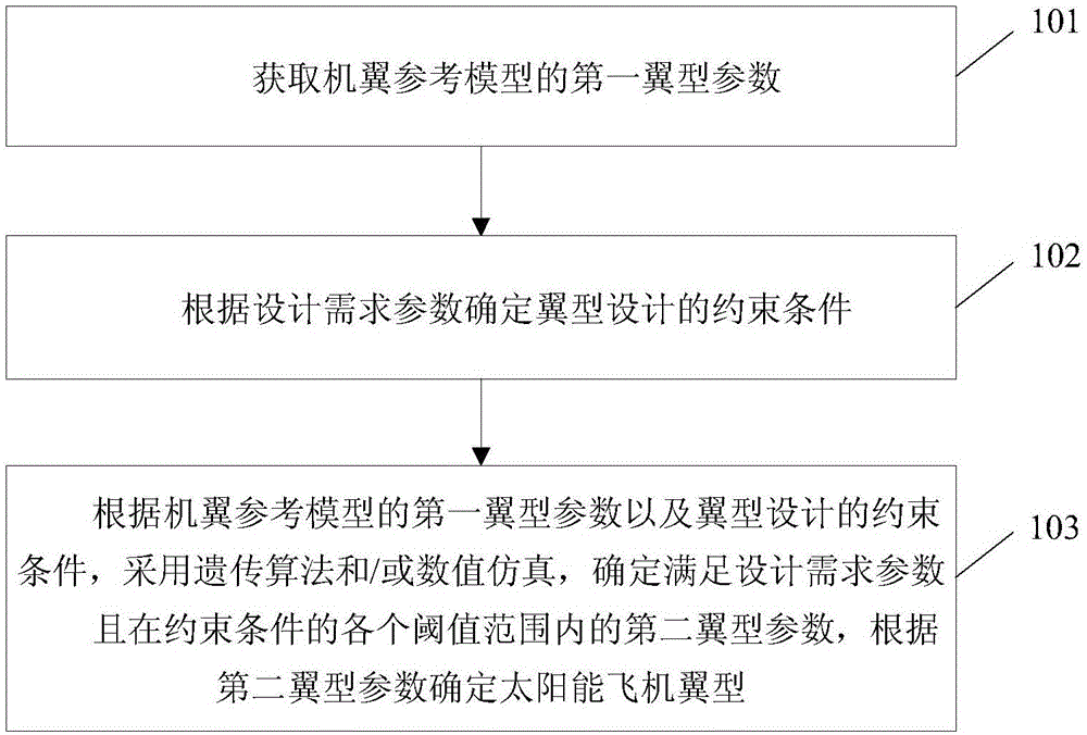
[0022] figure 1 The flow chart of the solar aircraft airfoil design method provided by Embodiment 1 of the present invention, such as figure 1 As shown, the solar aircraft airfoil design method includes:

[0023] Step 101. Obtain the first airfoil parameters of the wing reference model.

[0024] Specifically, the parameters of the first airfoil include: the maximum relative thickness of the first airfoil, the relative position of the maximum relative thickness of the first airfoil, the maximum relative camber of the first airfoil; the relative position of th...


PUM


Abstract

The invention provides a solar-powered airplane airfoil profile design method and a solar-powered airplane airfoil profile, wherein the method includes the steps: first airfoil profile parameters of an airfoil reference model are acquired, wherein the first airfoil profile parameters include a first airfoil profile maximum relative thickness, a relative position of the first airfoil profile maximum relative thickness, a first airfoil profile maximum relative camber, a relative position of the first airfoil profile maximum relative camber, and a first airfoil profile head radius; constraint conditions of an airfoil profile design are determined according to design demand parameters, wherein the design demand parameters include the flight speed, the elevating force coefficient and the Reynolds number, and the constraint conditions include a maximum relative thickness threshold, and an airfoil profile thickness threshold having the distance in the range of 20%-60% of the chord length away from an airfoil profile front edge; according to the first airfoil profile parameters of the airfoil reference model and the constraint conditions of the airfoil profile design and with use of a genetic algorithm and / or numerical simulation, second airfoil profile parameters meeting the design demand parameters and in the range of all the thresholds of the constraint conditions are determined, and the solar-powered airplane airfoil profile is determined according to the second airfoil profile parameters.

Description

technical field [0001] The invention relates to the field of airfoil design, in particular to a solar-powered aircraft airfoil design method and a solar-powered aircraft airfoil. Background technique [0002] Due to the characteristics of no fuel consumption and high flight altitude, solar-powered aircraft has always been a good platform for earth observation and communication relay services. At present, countries have invested a lot of manpower and funds in research on it. Among them, the airfoil of solar-powered aircraft is an important part related to the safety and aerodynamic performance of solar-powered aircraft. How to design the aerodynamic shape of solar-powered flying airfoil with high lift and low Reynolds number has always been a hot issue in this field. [0003] The airfoil design of a solar-powered aircraft usually needs to meet the requirements of improving the aerodynamic efficiency of the cruise point under different lift coefficients and different Reynolds ...

Claims


Application Information

Patent Timeline
Patent Type & Authority Applications(China)
IPC IPC(8): B64C3/14
Inventor 曾洪江白琳谢晋东
Owner BEIJING CHANGYUAN TECH
Why Eureka
Try Eureka