Special airfoil for blade tip of wind driven generator

A wind turbine and airfoil technology, applied in the field of wind turbine components, can solve the problems of the influence of the aerodynamic performance of the airfoil leading edge roughness, the small maximum lift coefficient and the like

Inactive Publication Date: 2010-11-17
CHONGQING UNIV
View PDF4 Cites 7 Cited by
  • Summary
  • Abstract
  • Description
  • Claims
  • Application Information

AI Technical Summary

Problems solved by technology

[0005] However, the maximum lift coefficient of an airfoil with a gentle stall performance is generally relatively small, while the airfoil with a large maximum lift coefficient often has a very sha

Method used


Image

  • Special airfoil for blade tip of wind driven generator
  • Special airfoil for blade tip of wind driven generator
  • Special airfoil for blade tip of wind driven generator

Examples


Embodiment Construction

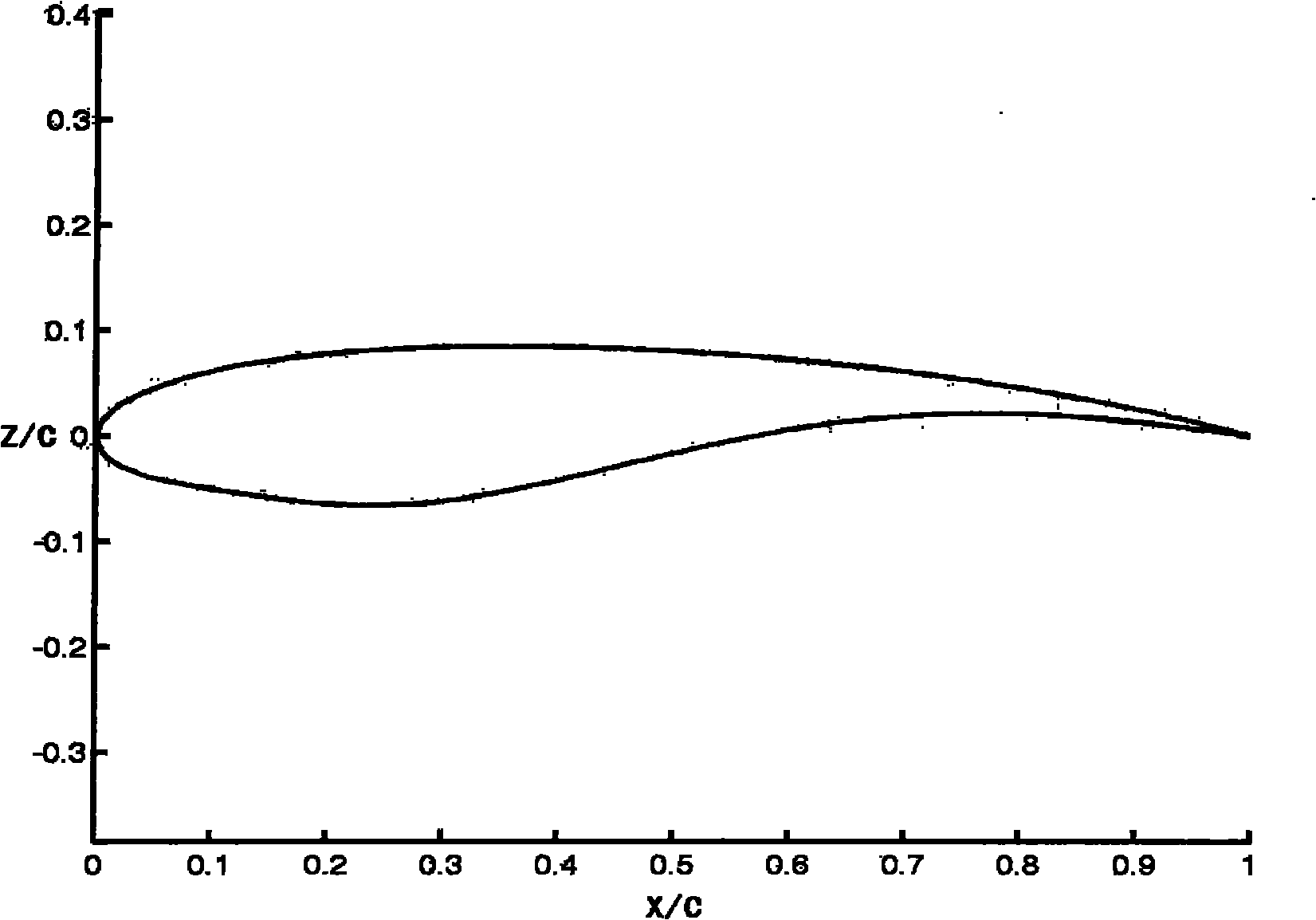
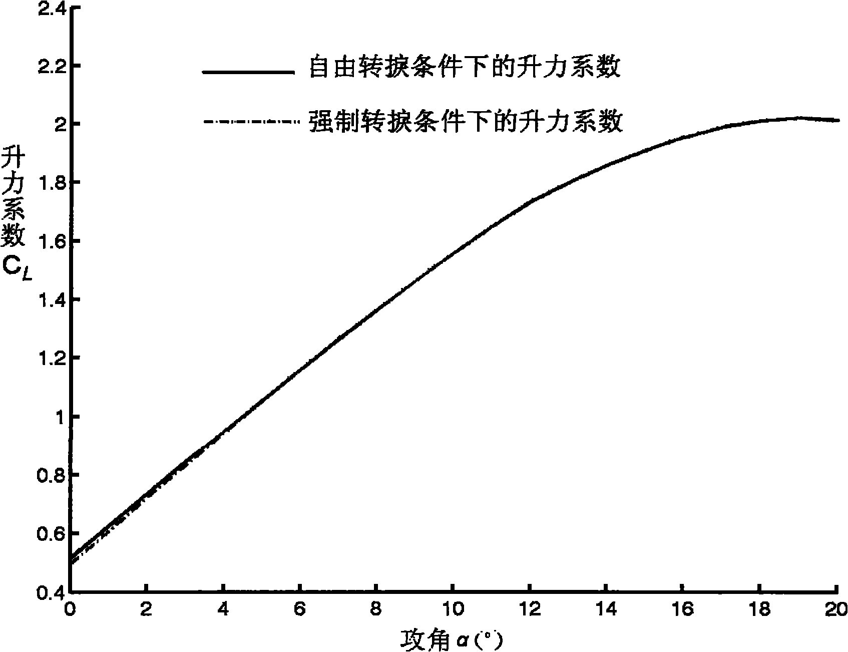
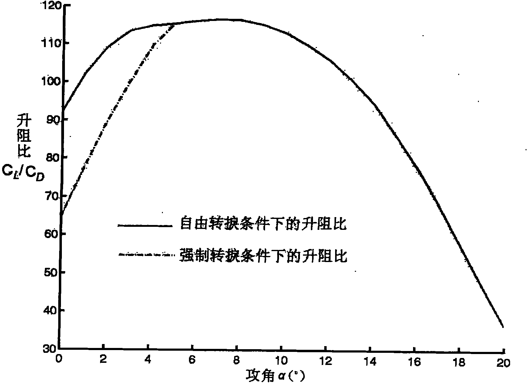
[0036] figure 1 is the airfoil diagram of the present invention, figure 2 Be the variation curve of the lift coefficient of the airfoil of the present invention with the angle of attack, image 3 It is the change curve of the lift-drag ratio of the airfoil of the present invention with the angle of attack, as shown in the figure: the airfoil dedicated to the blade tip of the wind power generator of the present embodiment, the airfoil adopts the PARSEC airfoil expression method, and the equation is When k=1, it represents the upper airfoil, and when k=2, it represents the lower airfoil. is the Z-axis coordinate of the airfoil, and X is the position along the chord length direction, To determine the parameters of the airfoil shape; the parameters 0.01up up xxup dw dw xxdw Substitute for The following two sets of 6-element equations can be obtained:

[0037] Equation one

[0038] a 1 1 = 2 r ...


PUM


Abstract

The invention discloses a special airfoil for a blade tip of a wind driven generator. In the invention, on the basis of the optimized airfoil molded line model, an airfoil molded line which is suitable for the blade tip is designed by using nine control parameters of the parsec airfoil expression method as variants. In the range of the normal working attack angle, the special airfoil has very high lift coefficient and lift-to-drag ratio and very slow stall performance; the front edge of the special airfoil has good roughness and non-sensitivity so that the wind turbine can still work normally even if the front edge is frozen or polluted. Thereby, the special airfoil meets the requirements of the pneumatic performance of the blade tip of the wind turbine.

Description

technical field [0001] The invention relates to a wind power machine component, in particular to a special airfoil for the blade tip of a wind power generator. Background technique [0002] As a green energy, wind energy is an effective means to solve energy problems, improve the ecological environment and reduce carbon dioxide emissions. A wind turbine is an intermediate device that converts wind energy into electrical energy and other energy sources. The wind turbine relies on the wind wheel to absorb wind energy. The aerodynamic performance of the blade airfoil of the impeller directly affects the efficiency of wind energy utilization by the wind turbine. [0003] Due to the influence of three-dimensional effects, the blade tip area of ​​wind turbine blades often produces complex flow phenomena, especially the generation of blade tip vortices will increase the velocity loss and reduce the power of the wind turbine. Without increasing the diameter of the wind turbine impe...

Claims


Application Information

Patent Timeline
IPC IPC(8): F03D11/00
CPCY02E10/722
Inventor 陈进陆群峰庞晓平任志贵
Owner CHONGQING UNIV
Why Eureka
Try Eureka