Bifacial feeding/discharging machine

A material machine, double-sided technology, applied in the field of double-sided material loading and unloading machine

Active Publication Date: 2015-12-09
LINGDI EQUIP
View PDF7 Cites 11 Cited by
  • Summary
  • Abstract
  • Description
  • Claims
  • Application Information

AI Technical Summary

Problems solved by technology

[0004] In the existing production line, the general loading and unloading machine only adopts one-way loading/unloading settings, and the grippers can only pick up the glass slides from the pr

Method used


Image

  • Bifacial feeding/discharging machine
  • Bifacial feeding/discharging machine
  • Bifacial feeding/discharging machine

Examples


Embodiment Construction

[0027] specific implementation plan

[0028] Further description will be given below in conjunction with the accompanying drawings and preferred embodiments of the present invention.

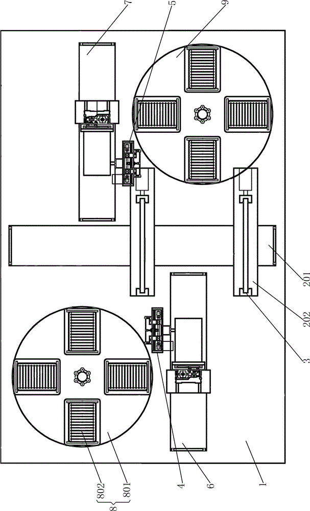
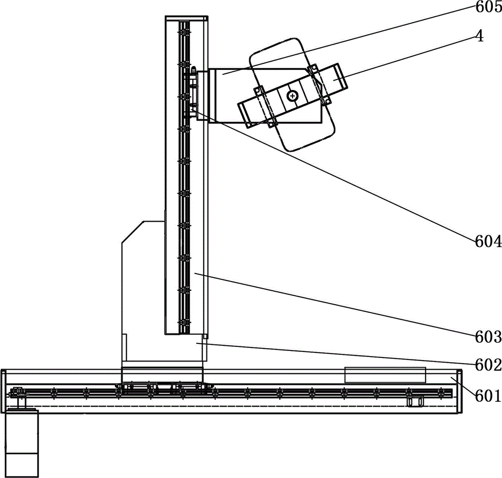
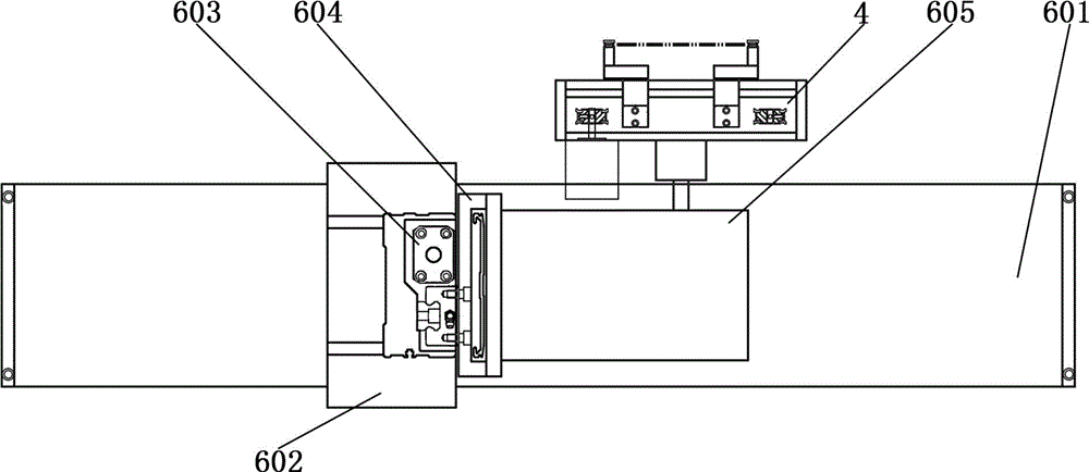
[0029] Such as figure 1As shown, a double-sided loading and unloading machine includes a frame 1, a jig driving mechanism (blocked and not marked in the figure), a jig moving shaft 201, a plurality of jig workbenches 202, jigs 3, and a first clamp Jaw 4, second jaw 5, first jaw driving mechanism 6, second jaw driving mechanism 7, first material receiving device 8 and second material receiving device 9; fixture driving mechanism (blocked and not marked in the figure ), the jig moving shaft 201, the first jaw driving mechanism 6, the second jaw driving mechanism 7, the first material receiving device 8 and the second material receiving device 9 are all installed on the frame, and the first material receiving device 8 and the second material receiving device 9 are respectively installed on both s...


PUM


Abstract

The invention relates to a bifacial feeding/discharging machine. The bifacial feeding/discharging machine is provided with a jig shifting shaft, a jig worktable, a jig and a jig driving mechanism, and thus, can be used for delivering a workpiece between the current feeding/discharging position and the next feeding/discharging position in a reciprocating mode; the feeding/discharging position and processing position are staggered, both sides of the jig shifting shaft are respectively provided with a clamping jaw driving mechanism and a receiving device, and the two clamping jaw driving mechanisms respectively drive clamping jaws; and simultaneous feeding or simultaneous discharging, or one-side feeding and one-side discharging can be set according to the practical production condition. The two clamping jaw driving mechanisms independently operate without interference, the jig can move on the jig workbench according to the positions of the clamping jaws, and the workpiece can be transported from the receiving device to the jig and delivered to the next processing position for processing, or transported from the jig to the receiving device after the processing is finished, thereby greatly shortening the transportation time of the workpiece between the receiving device and jig, and further enhancing the production efficiency.

Description

technical field [0001] The invention relates to a feeding device, in particular to a double-sided loading and unloading machine. Background technique [0002] In the manufacturing industry of flat glass products such as liquid crystal display screens and touch screens, it is necessary to remove the glass slide from the relevant device of the previous process, transport it to the next process, and place it at a specific angle on the relevant device of the next process. In the device, for example, the slide is taken out of the slide basket and transported to the glass fixture on the workbench. [0003] At present, in the glass plate product manufacturing industry, the structure of the loading and unloading machine generally includes a frame, a gripper, a gripper driving mechanism and a material receiving device. Both the gripper driving mechanism and the material receiving device are installed on the frame. Installed on the power output end of the jaw driving mechanism, the j...

Claims


Application Information

Patent Timeline
IPC IPC(8): B65G47/90B65G49/06
Inventor 魏家华孙名伟吴礼丹
Owner LINGDI EQUIP
Why Eureka
Try Eureka