Steel pipe lifting and taking device

A steel pipe and vertical arm technology, which is applied in the field of steel pipe lifting and taking devices, can solve the problems of high energy consumption, inconvenient control, complex structure, etc., and achieve the effects of convenient use, easy control, and simple and reasonable structure.

Inactive Publication Date: 2015-12-09
刘洋
View PDF7 Cites 23 Cited by
  • Summary
  • Abstract
  • Description
  • Claims
  • Application Information

AI Technical Summary

Problems solved by technology

The device currently used for steel pipe transportation has a relatively complicated structure, is not easy to control, and consumes a lot of energy

Method used


Image

  • Steel pipe lifting and taking device

Examples


Embodiment Construction

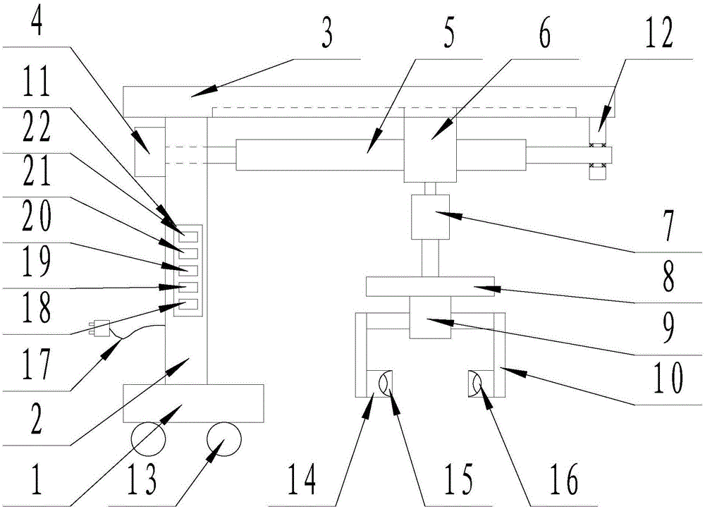
[0013] The present invention will be specifically described below in conjunction with the accompanying drawings, such as figure 1 As shown, a steel pipe lifting and taking device comprises a base (1), a vertical arm (2) is arranged on the base (1), a support plate (3) is arranged on the upper end of the vertical arm (2), and the The lower surface of the support plate (3) is provided with a sliding rail, the upper end of the vertical arm (2) is provided with a rotating motor (4), and the rotating end of the rotating motor (4) is provided with a roller screw (5). The upper sleeve of the shaft screw (5) can move along its length direction, and the upper end is embedded in the motion box (6) in the slide rail, the lower surface of the motion box (6) is provided with a linear motor (7), the linear motor (7) The telescopic end of the motor (7) is provided with a bracket (8), the bracket (8) is provided with a bidirectional cylinder (9), and a pair of piston rods of the bidirectional...


PUM


Abstract

The invention discloses a steel pipe lifting and taking device. The steel pipe lifting and taking device comprises a base. A vertical arm is arranged on the base. A supporting plate is arranged at the upper end of the vertical arm. A sliding rail is arranged on the lower surface of the supporting plate. A rotary motor is arranged at the upper end of the vertical arm, and a roller screw is arranged at the rotation end of the rotary motor. The roller screw is sleeved with a movable box which can move in the length direction, and the upper end of the movable box is embedded in the sliding rail. A linear motor is arranged on the lower surface of the movable box. A supporting seat is arranged at the telescopic end of the linear motor and provided with a bi-directional air cylinder. A pair of piston rods of the bi-directional air cylinder are provided with vertical rods respectively, and the pair of vertical rods are provided with supporting claws. The vertical arm is provided with a control panel. The control panel is electrically connected with the rotary motor, the linear motor and the bi-directional air cylinder. The steel pipe lifting and taking device has the beneficial effects of being simple in structure and high in practicability.

Description

technical field [0001] The invention relates to the field of mechanical transportation, in particular to a steel pipe lifting and taking device. Background technique [0002] At present, steel pipes are not only used for conveying fluids and powdered solids, exchanging thermal energy, manufacturing mechanical parts and containers, but also an economical steel. Using steel pipes to make building structure grids, pillars and mechanical supports can reduce weight, save metal by 20 to 40%, and realize factory mechanized construction. At present, the device used for steel pipe conveying has a complex structure, which is inconvenient to control and consumes a lot of energy. SUMMARY OF THE INVENTION [0003] The purpose of the present invention is to design a steel pipe lifting and taking device in order to solve the above problems. [0004] The technical solution of the present invention to achieve the above object is that a steel pipe lifting and taking device includes a base...

Claims


Application Information

Patent Timeline
Patent Type & Authority Applications(China)
IPC IPC(8): B65G47/91
Inventor 刘洋
Owner 刘洋
Why Eureka
Try Eureka