Electric binding wire coiling device

A wire binding and electric technology, which is applied in the field of electric wire binding coilers, can solve the problems of easy fatigue of workers, low efficiency of manual operation, and difficulty in guaranteeing winding quality, so as to solve the risk of electric shock injury, improve maintenance efficiency, and improve the efficiency of winding. Effects of Line Specifications

Inactive Publication Date: 2015-12-09
STATE GRID CORP OF CHINA +1
View PDF1 Cites 1 Cited by
  • Summary
  • Abstract
  • Description
  • Claims
  • Application Information

AI Technical Summary

Problems solved by technology

Although this patent solves the safety problem and improves work efficiency to a certain extent, the efficiency of manual operation is not high, and workers are prone to fatigue during operation, and the winding quality is difficult to guarantee.

Method used


Image

  • Electric binding wire coiling device

Examples


Embodiment Construction

[0011] The following will clearly and completely describe the technical solutions in the embodiments of the present invention with reference to the accompanying drawings in the embodiments of the present invention. Obviously, the described embodiments are only some, not all, embodiments of the present invention. Based on the embodiments of the present invention, all other embodiments obtained by persons of ordinary skill in the art without making creative efforts belong to the protection scope of the present invention.

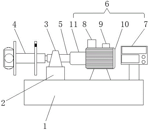
[0012] The present invention provides such as figure 1 The shown electric wire binding coiler includes a chassis 1, a base 2, a bearing seat 3, a reel device 4, a rotating shaft 5 and a servo control device 6, the base 2 is fixed on the top of the chassis 1, and the bearing seat 3. The bottom is fixedly connected with the base 2 through screws and bolts. The reel device 4 is fixedly connected with the left end of the rotating shaft 5. The reel device 4 include...


PUM


Abstract

The invention discloses an electric binding wire coiling device. The electric binding wire coiling device comprises a case, a base, a bearing block, a coiling block device, a rotating shaft and a servo control device. An NC is fixedly connected with the right end of the case through a support. A servo controller is electrically connected with the NC and a servo motor through wires. An encoder is arranged on the right side of the upper end of the servo motor and electrically connected with the servo controller and the servo motor. The servo motor is arranged at the upper end of the case through the support. The servo motor is rotationally connected with a speed reducer. The speed reducer is rotationally connected with the rotating shaft through a bearing. By means of the electric binding wire coiling device, the efficiency of winding of a binding wire is greatly improved, the wound binding wire is standard and neat, and usage for the work field is convenient. Meanwhile, an original manual binding wire winding manner is thoroughly changed, the work efficiency is improved, and the labor intensity is relieved.

Description

technical field [0001] The invention belongs to the technical field of electric equipment, and in particular relates to an electric wire binding coiler. Background technique [0002] In the power industry, the binding wire is the most widely used. When winding the binding wire, it is usually wound manually, that is, one hand of the operator holds one end of the binding wire tightly, and the other hand wraps the binding wire around the hand. Rotate to complete the wrapping of the binding wire. However, due to the different sizes of the binding wires, manual winding is time-consuming and laborious, and there will be dead bends in the binding wires after winding, thereby reducing the winding quality of the binding wires, making the binding wires unusable and causing waste. For example, the Chinese patent application number 201320459235.8 discloses an aluminum binding wire winder, which includes a base, a handle and a screw rod for fixing the base. The base is bow-shaped, and t...

Claims


Application Information

Patent Timeline
Patent Type & Authority Applications(China)
IPC IPC(8): B65H75/28B65H75/14B65H75/32B65H54/28B65H54/44
Inventor 孙志彬王栋俞迎新韩梅梅张艳霞
Owner STATE GRID CORP OF CHINA
Why Eureka
Try Eureka