
Push-pull hook

A push-pull hook and connecting frame technology, which is applied in the field of push-pull hooks, can solve problems such as easy to drop, impractical, and prone to safety accidents, and achieve the effects of preventing items from falling off, good practical effect, and small space occupation

Active Publication Date: 2015-12-09
长治市永华机械有限公司
View PDF6 Cites 4 Cited by
  • Summary
  • Abstract
  • Description
  • Claims
  • Application Information

AI Technical Summary

Problems solved by technology

[0002] The positioning machine of the hydraulic support is equipped with a push-pull hook. In the process of use, the hook body is inconvenient to disassemble. practical

Method used


Image

  • Push-pull hook
  • Push-pull hook
  • Push-pull hook

Examples


Embodiment Construction

[0014] The present invention will now be further described in detail in conjunction with the accompanying drawings. The accompanying drawings are simplified schematic diagrams, which only schematically illustrate the basic structure of the present invention, and therefore only show the configurations related to the present invention.

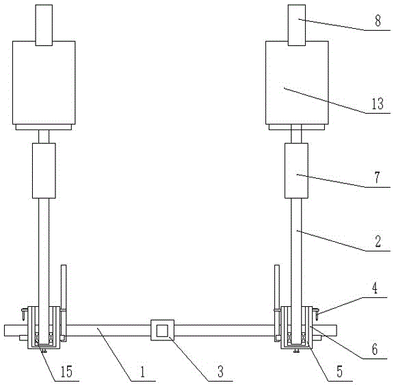
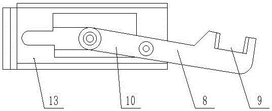
[0015] Such as Figure 1-3 As shown, the push-pull hook includes a lower bracket 1 and a rocker 2 connected to both ends of the lower bracket 1. The rocker 2 can rotate relative to the lower bracket 1. The connecting frame rocker 2 is set on the lower bracket 1 and locked by a pin 4. According to actual production and use needs, the installation positions of the rocker arm 2 and the lower support 1 can be adjusted through the pin 4 to adapt to the hydraulic support. The middle part of the lower bracket 1 of the connection frame is connected by the connection seat 3, the first connection frame 5 and the second connection frame 6 are arranged on b...


PUM


Abstract

The invention belongs to the technical field of push-pull hooks, and particularly relates to a push-pull hook applied to a hydraulic support. According to the specific technical scheme, the push-pull hook comprises a lower support and rockers connected to the two ends of the lower support, and the rockers can rotate relative to the lower support. The rockers are arranged on the lower support in a sleeving manner and locked through pins. According to the actual production and usage requirements, the installing positions of the rockers and the lower support can be adjusted through the pins to adapt to the hydraulic support. The middle of the connecting frame lower support is connected through a connecting base. Each of the two sides of each connecting frame rocker is provided with a first connecting plate and a second connecting frame, wherein the connecting frame second connecting frame is arranged on the outer side of a first connecting frame. The top ends of the connecting frame rockers are connected with oil cylinders, and the bottoms of cylinder barrels of the oil cylinders are fixed to the rockers. Cylinder rods of the connecting frame oil cylinders externally extend into the base and are connected with a hook body, and the hinge position and the hooking direction of the hook body can be adjusted through the oil cylinders.

Description

technical field [0001] The invention belongs to the technical field of push-pull hooks, in particular to a push-pull hook applied to hydraulic supports. Background technique [0002] The positioning machine of the hydraulic support is equipped with a push-pull hook. In the process of use, the hook body is inconvenient to disassemble. practical. Contents of the invention [0003] The invention overcomes the disadvantages of the prior art, and aims to provide a push-pull hook applied to a hydraulic support, which occupies a small space and is convenient to disassemble and assemble. [0004] In order to solve the above technical problems, the technical solution adopted in the present invention is: a push-pull hook, including a lower bracket and a rocker arm connected to both ends of the lower bracket, the rocker arm can rotate relative to the lower bracket, and the rocker arm is sleeved on the lower bracket and locked by a pin , according to the actual production and use ne...

Claims


Application Information

Patent Timeline
IPC IPC(8): B66C1/22B66C13/08
Inventor 常补孩赵庆枝刘旭明王海斌司天善原磊明孔仁山马宵立王晓东
Owner 长治市永华机械有限公司
Learn More