

Uplift pile
A technology for uplift piles and pile bodies, which is applied in sheet pile walls, buildings, infrastructure engineering and other directions, can solve the problems of complex manufacturing process and need to be further improved in uplift resistance, so as to achieve the effect of improving the uplift resistance.
- Summary
- Abstract
- Description
- Claims
- Application Information
AI Technical Summary
Problems solved by technology
Method used
Image

Examples
Embodiment 1
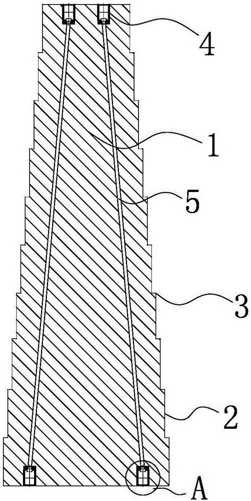
[0031] Such as figure 1 As shown, an uplift pile includes a pile body 1, and the pile body 1 is formed by connecting several sections of pile bodies 2 whose cross-sectional areas gradually increase from top to bottom, and every two adjacent pile bodies 2 The connection forms a stepped portion 3 .
[0032] Preferably, the cross section of the pile body 2 is square, H-shaped, triangular, circular, hexagonal or octagonal. The ratio of the cross-sectional area of the pile body 2 at the top of the pile body 1 to the cross-sectional area of the pile body 2 at the bottom of the pile body 1 is 1:4-10. The plane where the surface of the step portion 3 is located is perpendicular to the axis of the pile body 1 . The height of each pile body 2 is the same.
[0033] Preferably, several connecting nuts 4 are fixed at both ends of the pile body 1, and several connecting ribs 5 are arranged in the pile body 1, and the two ends of the connecting ribs 5 are respectively fixedly connecte...
Embodiment 2
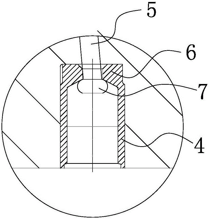
[0038] The structure and principle of this embodiment are basically the same as Embodiment 1, the difference is that, as Figure 4 and Figure 11 As shown, the bottom of the connecting nut 4 is provided with a tapered cavity, and the cavity is provided with a tapered snap ring 9 composed of at least two cards 8. The inner wall of the card 8 has a concave-convex structure, and the connecting rib 5 The end is placed in the clasp 9 and clamped by the inner wall of the card 8 . The connecting rib 5 is a steel rod, a steel bar, a chemical profile, a carbon fiber rod, but it is preferably a steel strand, which is convenient to clamp with the snap ring 9.
[0039] The inner wall of the connecting nut 4 above the snap ring 9 has an internal thread, and the bottom of the connecting nut 4 and below the snap ring 9 has a flange ring 10 .
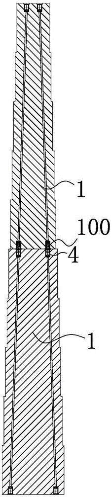
[0040] Such as Figure 6 As shown, when two adjacent pile bodies 1 need to be connected, they are connected through a connecting piece 100 , and th...
Embodiment 3
[0042] The structure and principle of this embodiment are basically the same as Embodiment 2, the difference is that, as Figure 5 As shown, the two ends of the pile body 1 are respectively provided with an end plate 11 fixedly connected with the pile body 1, as Figure 10 As shown, the end plate 11 is provided with a plurality of tapered fastener holes 12, and the tapered fastener holes 12 are provided with a tapered snap ring 9 composed of at least two cards 8, and the inner wall of the card 8 has a concave-convex shape. structure, the end of the connecting rib 5 is placed in the snap ring 9 and is clamped by the inner wall of the card 8.
[0043] When the above-mentioned pile body 1 needs to be connected, such as Figure 7 As shown, two adjacent end plates 11 can be tightened with bolts, and of course the adjacent end plates 11 can also be welded.
[0044] preferred options, such as Figure 9 As shown, the end plate 11 is provided with a connecting hole 13 with a T-shape...
PUM
 Abstract
Description
Claims
Application Information