Pipe joint structure

A technology for pipe joints and structures, applied in the direction of pipes/pipe joints/fittings, sealing surface connections, passing components, etc., can solve the problems of complex shapes, time-consuming, and large number of parts, and achieve simple shapes of parts and easy operation. The effect of high efficiency and easy assembly

Active Publication Date: 2015-05-13
INOUE SUDARE +1
View PDF8 Cites 4 Cited by
  • Summary
  • Abstract
  • Description
  • Claims
  • Application Information

AI Technical Summary

Problems solved by technology

In the case where the tube 35 is made of aluminum, there is the disadvantage that it is difficult to perform bell mouth processing
Of course, even in the case of copper pipes, the above-mentioned bell mouth processing needs to be performed on site, so there is a disadvantage that the efficiency of piping work is hindered.
In addition, in order to avoid these problems, various pipe joint structures have been proposed, but there are disadvantages such as a large number of parts, the need for parts with complicated shapes, and labor-intensive assembly.

Method used


Image

  • Pipe joint structure
  • Pipe joint structure
  • Pipe joint structure

Examples


Embodiment Construction

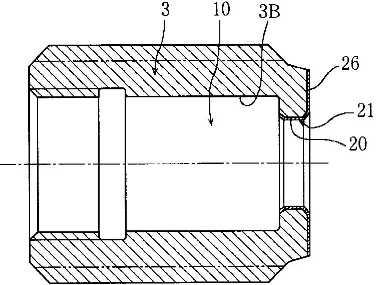
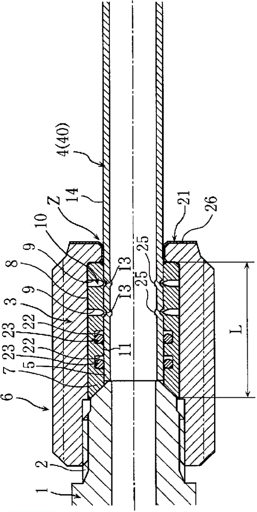
[0037] figure 1 The state before the connection of the aluminum pipe of 1st Embodiment of this invention is shown. figure 2 Shows the connection completion status. The pipe joint structure is a joint body 1 with an external thread and a cap nut 3 screwed on the external thread 2 to connect the aluminum pipe 4, and its structure is especially suitable for piping for refrigerants. The aluminum pipe 4 and the pipe joint 6 can be connected without performing flare processing on the end portion 5 of the aluminum pipe 4 . The joint main body 1 and the cap nut 3 are made of brass, for example. A refrigerant / refrigerant of an air conditioner or the like flows through the aluminum pipe 4 and the pipe joint 6 .

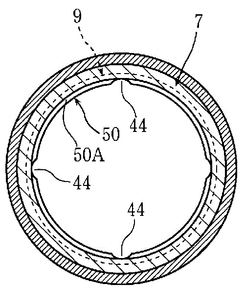
[0038] image 3 (A) shows the sleeve 7 for compression deformation made of aluminum. The sleeve 7 for compression deformation has two U-shaped concave peripheral grooves 9 on the outer peripheral surface 8 . Such as figure 1 , figure 2 As shown, the compression defo...


PUM


Abstract

To provide a pipe joint construction with which swift and strong connection is possible without flare work on an end portion when a pipe composed of aluminum, a pipe joint construction provided with a joint main body 1 with a male screw and a cap nut 3 screwed to a male screw 2 of the joint main body 1 to connect an aluminum pipe 4, has a cylindrical compressed deformation sleeve 7, stored in an inner storing space 10 of the cap nut 3 and having a concave peripheral groove 9 on a peripheral face 8, in which a bottom thin wall portion 13 of concave groove, receiving compressing force F in axial direction from the joint main body 1 and the cap nut 3 when the cap nut 3 and the male screw 2 of the joint main body are screwed, is plastically deformed in a radial inner direction to bite into a peripheral face 14 of an inserted aluminum pipe 4 for stopping the aluminum pipe 4.

Description

technical field [0001] The present invention relates to a pipe joint structure. Background technique [0002] As one of the pipe joints, flared pipe joints are widely used (for example, refer to Patent Document 1). [0003] Generally, its structure is as follows Figure 11 As shown, the bell mouth end 37 formed by plastically processing the end of the copper pipe 35 in an enlarged diameter cone shape is clamped on the tapered surface 31 of the joint body 30 with external threads and screwed on the joint body. 30 on the external thread 32 of the cap nut 33 on the tapered surface 34, and by means of crimping force to seal. [0004] However, in recent years, as a material of the tube 35 , it has been strongly desired to use aluminum which is cheap and lightweight rather than copper which is expensive and heavy. In the case where the pipe 35 is made of aluminum, there is a disadvantage that it is difficult to implement the bell mouth machining. Of course, even in the case of ...

Claims


Application Information

Patent Timeline
Patent Type & Authority Applications(China)
IPC IPC(8): F16L19/08
CPCF16L19/065F16L19/10F16L19/12
Inventor 井上智史
Owner INOUE SUDARE
Why Eureka
Try Eureka