LED mirror front lamp

A technology of mirror headlights and lamp holders, which is applied in the field of mirror headlights, can solve the problems of LED chips not being resistant to high temperature, inconvenient installation and disassembly of mirror headlights, etc., and achieves convenient and quick disassembly, cleverness involved, and improved energy utilization rate effect

Active Publication Date: 2015-12-09
JIANGSU SHUSHI LIGHTING CO LTD
View PDF6 Cites 0 Cited by
  • Summary
  • Abstract
  • Description
  • Claims
  • Application Information

AI Technical Summary

Problems solved by technology

A conductor is fixed at the end of the plastic part of the lamp head of the LED mirror headlight, and the conductor is electrically connected to the light source board. However, the mirror headlight with this structure is inconvenient to install. When the circuit breaks down and needs to be disassembled for maintenance, it is very inconvenient to disassemble. and not safe
Due to the limitation of LED packaging materials on the market, the temperature of the bracket cannot exceed 120°C (EMC material) during the production and assembly process of LED mirror lamps on the market, so they all use plastic or glass plus plastic lampshades, which have low luminous efficiency and large light decay.
[0003] Lighting companies such as Philips and Osram failed to solve the contradiction between glass flame melting, high-temperature annealing and LED chips not being resistant to high temperatures, so the existing all-glass mirror headlights still use traditional tungsten filaments to heat and emit light. The powder coating on the inner wall enhances the diffusion and uniformity, and the luminous efficiency is only about 35LM\W. It is time to withdraw from the lighting market

Method used


Image

  • LED mirror front lamp
  • LED mirror front lamp
  • LED mirror front lamp

Examples


Embodiment Construction

[0022] The content of the present invention will be further described in detail below in conjunction with the accompanying drawings.

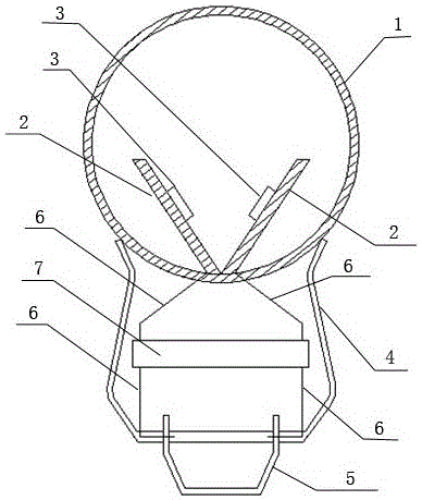
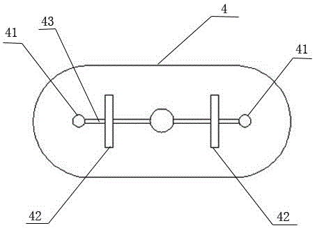
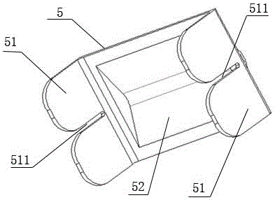
[0023] like figure 1 As shown, a clip-on LED mirror headlight includes a lampshade 1, a light source board, a lamp holder plastic part 4, hardware parts 5, wires 6, and a driving board 7. The cross-section of the lamp cap plastic part 4 is a U-shaped structure, such as figure 2 As shown, a threading hole 41 is respectively provided on both sides of the lower end surface of the lamp holder plastic part 4 , and two bayonets 42 are provided on the opposite inner sides of the two threading holes 41 . The lampshade 1 is installed on the upper end surface of the lamp holder plastic part 4 . The light source board is arranged in the lampshade 1, and the light source board includes an aluminum substrate 2 and an LED light source board 3. The driving board 7 is installed in the plastic part 4 of the lamp cap. like image 3 As shown, the hardware 5...


PUM


Abstract

The invention discloses an LED mirror front lamp. The LED mirror front lamp comprises a lampshade, light source plates, a lamp cap plastic part, hardware, a driving board and wires. Two wiring holes are formed in the two sides of the lower end face of the lamp cap plastic part respectively, and two bayonets are formed in the opposite inner sides of the two wiring holes; the lampshade is installed on the upper end face of the lamp cap plastic part, the light source plates are arranged in the lampshade, and each light source plate comprises an aluminum substrate and LED lamp beads; clamping side pieces are arranged at the two sides of the hardware, a gap is formed in the middle of each clamping side piece, and the clamping side pieces at the two sides of the hardware are inserted into the bayonets in the lower end face of the lamp cap plastic part; the driving board is installed in the lamp cap plastic part; the number of the wires is four, two wires are connected to the driving board through the light source plates respectively, and the other two wires extend from the driving board, penetrate through the wiring holes in the lower end face of the lamp cap plastic part and finally are clamped to the gaps in the clamping side pieces of the hardware. The LED mirror front lamp is convenient and fast to assemble and disassemble and high in safety.

Description

technical field [0001] The invention relates to a mirror headlight, in particular to an LED mirror headlight. Background technique [0002] At present, the existing domestic low-end LED mirror lamps are composed of plastic lampshades, light source boards (radiating bodies), lamp holder plastic parts and other structural parts glued or screwed. A conductor is fixed at the end of the plastic part of the lamp head of the LED mirror headlight, and the conductor is electrically connected to the light source board. However, the mirror headlight with this structure is inconvenient to install. When the circuit breaks down and needs to be disassembled for maintenance, it is very inconvenient to disassemble. And it's not safe. Due to the limitation of LED packaging materials, the LED lamps in front of the mirror on the market cannot exceed 120°C during the production and assembly process (EMC material), so they all use plastic or glass plus plastic lampshades, which have low luminous...

Claims


Application Information

Patent Timeline
Patent Type & Authority Applications(China)
IPC IPC(8): F21S8/00F21V17/16F21V27/02F21V3/04F21V29/89F21V29/85F21V23/00F21V29/71F21Y101/02
CPCF21S8/00F21V17/16F21V23/002F21V27/02
Inventor 张海成谢红桂荀月建
Owner JIANGSU SHUSHI LIGHTING CO LTD
Why Eureka
Try Eureka