
A high and low temperature infrared confocal, large aperture, small volume optical system

An infrared confocal and optical system technology, which is applied in the field of optical systems, can solve problems such as image sharpness and color reproduction, poor adaptability to high and low temperatures, poor imaging quality, etc., and achieve good image sharpness and color reproduction, Good adaptability and cost reduction effect

Active Publication Date: 2017-06-30
UNION OPTECH
View PDF9 Cites 0 Cited by
  • Summary
  • Abstract
  • Description
  • Claims
  • Application Information

AI Technical Summary

Problems solved by technology

[0004] At present, the lenses used in monitoring generally have such shortcomings: the lens has poor adaptability to high and low temperature, infrared non-confocal, high cost, small aperture, large volume, etc.
Specifically, existing zoom lenses generally do not have infrared confocal function because they can be adjusted in focus, and have poor adaptability to high and low temperatures. When the image is cleared during the day, the image will appear blurred in the infrared at night, or the temperature during the day is relatively low. High, even when the temperature is low at night, the picture is blurred, and someone needs to assist in focusing from time to time, which is a serious waste of human resources. Moreover, the current high-pixel surveillance lens is prone to imbalance in image sharpness and color reproduction, and the image quality is poor.
At present, there are only a few lenses that improve a certain characteristic at the expense of other characteristics. For example, in order to achieve high and low temperature, infrared confocal and high pixels, a large number of glass spherical lenses or glass aspherical lenses are used, which improves the performance of the lens. cost, unable to meet the low-cost needs of consumers

Method used


Image

  • A high and low temperature infrared confocal, large aperture, small volume optical system
  • A high and low temperature infrared confocal, large aperture, small volume optical system
  • A high and low temperature infrared confocal, large aperture, small volume optical system

Examples


Embodiment Construction

[0019] The present invention will be further described below in conjunction with accompanying drawing:

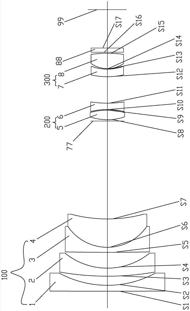
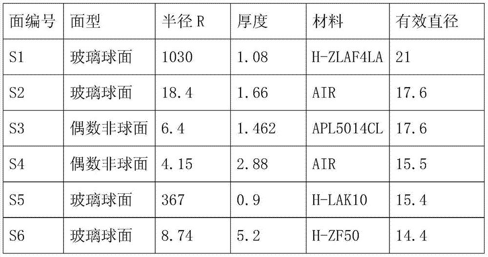
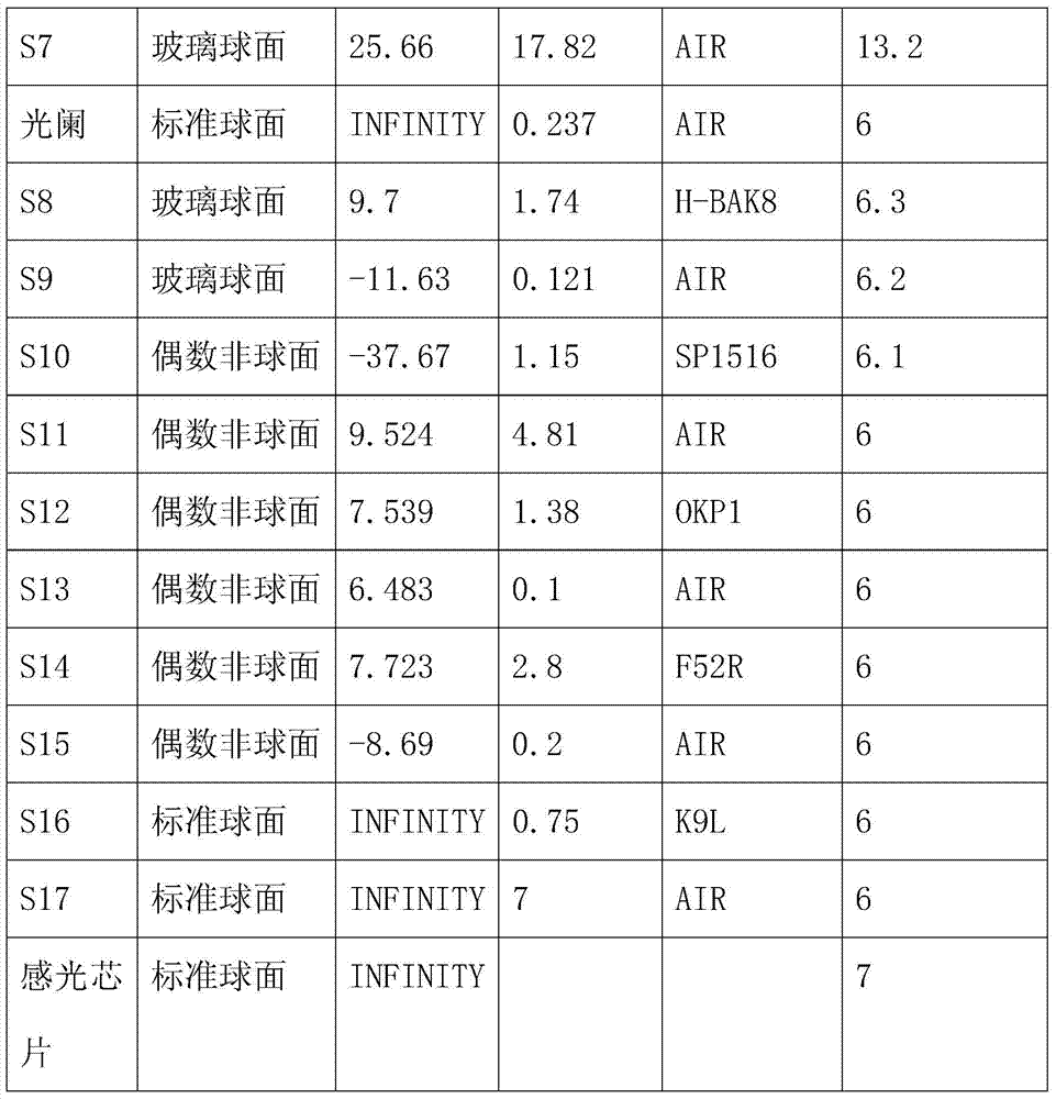
[0020] A high and low temperature infrared confocal, large aperture, small-volume optical system, comprising a diaphragm 77, a photosensitive chip 99 and an optical filter 88 between the two. The first lens group 100 that the diaphragm 77 moves back and forth, the second lens group 200 is provided between the diaphragm 77 and the filter 88, and the second lens group 200 and the filter 88 are provided The third lens group 300 that can move back and forth relative to the second lens group 200, the first lens group 100 includes the first lens 1, the second lens 2, the third lens 3, the second lens arranged in order from the object side to the image side Four lenses 4, the focal lengths of the first lens 1, the second lens 2 and the third lens 3 are all negative, the focal length of the fourth lens 4 is positive, and the second lens group 200 includes from the object The fifth...


PUM


Abstract

The invention discloses an optical system, which includes a diaphragm, a photosensitive chip and a filter. A first lens group that can move relative to the diaphragm is provided on the side of the diaphragm close to the object side. A second lens group is arranged between the diaphragm and the filter. Two lens groups, a third lens group capable of moving relative to the second lens group is provided between the second lens group and the optical filter, the first lens group includes a first lens, a second lens, a third lens, and a fourth lens, The focal lengths of the first lens, the second lens and the third lens are all negative, the focal length of the fourth lens is positive, the second lens group includes the fifth lens and the sixth lens, the focal length of the fifth lens is positive, and the focal length of the sixth lens is positive. The focal length is negative, the third lens group includes the seventh lens and the eighth lens, the focal length of the seventh lens is negative, the focal length of the eighth lens is positive, the first lens, the second lens, the third lens and the seventh lens are all A meniscus lens with the concave surface facing the image side. The invention has high and low temperature, infrared confocal, high pixel, low cost, large aperture and small volume.

Description

[0001] 【Technical field】 [0002] The invention relates to an optical system, more specifically a high and low temperature infrared confocal, large aperture, and small-volume optical system. [0003] 【Background technique】 [0004] At present, the lenses used in surveillance generally have such shortcomings: poor adaptability to high and low temperature, non-confocal infrared, high cost, small aperture, and large volume. Specifically, existing zoom lenses generally do not have infrared confocal function because they can be adjusted in focus, and have poor adaptability to high and low temperatures. When the image is cleared during the day, the image will appear blurred in the infrared at night, or the temperature during the day is relatively low. High, even when the temperature is low at night, the picture is blurred, and someone needs to assist in focusing from time to time, which is a serious waste of human resources. Moreover, the current high-pixel surveillance lens is prone...

Claims


Application Information

Patent Timeline
Patent Type & Authority Patents(China)
IPC IPC(8): G02B13/18G02B13/00
Inventor 刘勇辉李建华王晓王玉荣全丽伟潘华彭同山王世勇贾丽娜龚俊强
Owner UNION OPTECH
Learn More