Object lens of microscope
A microscope objective lens and lens group technology, applied in the microscope field, can solve the problems of excessive thickness and refractive index changes, affecting the quality of microscope imaging, etc., and achieve the effect of clear imaging
- Summary
- Abstract
- Description
- Claims
- Application Information
AI Technical Summary
Problems solved by technology
Method used
Image

Examples
Embodiment 1
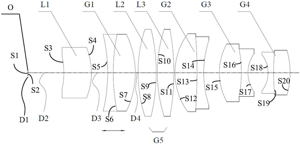
[0056] see figure 1 , the microscope objective lens of Example 1 of the present invention includes first lens L1 with positive refractive power, first lens group G1 with positive refractive power, second lens group G5 with positive refractive power, and negative optical power from the object side. The third lens group G2 with power, the fourth lens group G3 with negative refractive power, and the fifth lens group G4 with negative refractive power. The first lens group G1 is used to move along the optical axis of the objective lens to change the focal length of the objective lens.
[0057]When in use, the specimen is set on the object side S1 of the medium O (such as a cover glass), and the light reflected by the specimen is projected on the image plane S2 of the medium O, and then enters the microscope objective lens and the tube lens arranged on the side of the microscope objective mirror into the observer’s on the eye or image sensor (not shown). When measuring different s...
Embodiment 2
[0104] Please refer to Image 6 The microscope objective lens in Example 2 of the present invention is basically the same as the microscope objective lens in Example 1, but the fifth lens group G4 of the microscope objective lens in Example 2 includes a fourth lens L4, and correspondingly, the surface number of the microscope objective lens changes.
[0105] In addition, in Example 2, the microscope objective lens meets the conditions of the following table:
[0106] table 3
[0107] the surface
Radius (mm)
Thickness (mm)
Nd
Vd
S1
infinity
D1
1.52
64.2
S2
infinity
D2
S3
-2.1
0.4
1.82
60
S4
-0.98
D3
S5
-225
0.111
158
57.1
S6
1.365
0.443
1.52
70
S7
-2.86
D4
S8
3.73
0.3
1.43
95
S9
-2.16
0.022
S10
3.19
0.3
1.43...
Embodiment 3
[0117] Please refer to Figure 11 The microscope objective lens in Example 3 of the present invention is basically the same as the microscope objective lens in Example 1, but the second lens group G5 of the microscope objective lens in Example 3 includes the second lens L2, and correspondingly, the surface number of the microscope objective lens changes.
[0118] In addition, in embodiment 3, the microscope objective lens satisfies the condition of the following table:
[0119] table 5
[0120] the surface
Radius (mm)
Thickness (mm)
Nd
Vd
S1
infinity
D1
1.52
64.2
S2
infinity
D2
S3
-2.1
0.462
1.73
52.3
S4
-0.98
D3
S5
-4.275
0.11
1.57
58.8
S6
1.469
0.44
1.49
85.2
S7
-1.94
D4
S8
2.55
0.55
1.7
57.7
S9
-2.9
.022
S10
1.4...
PUM
 Abstract
Description
Claims
Application Information
 - Generate Ideas
- Intellectual Property
- Life Sciences
- Materials
- Tech Scout
- Unparalleled Data Quality
- Higher Quality Content
- 60% Fewer Hallucinations
Browse by: Latest US Patents, China's latest patents, Technical Efficacy Thesaurus, Application Domain, Technology Topic, Popular Technical Reports.
© 2025 PatSnap. All rights reserved.Legal|Privacy policy|Modern Slavery Act Transparency Statement|Sitemap|About US| Contact US: help@patsnap.com