
Flat-touch screen and manufacturing method thereof

A manufacturing method and touch screen technology, which are applied in the fields of instruments, electrical digital data processing, and data processing input/output processes, etc., can solve the problems of wasting labor, the upper conductive layer is easily scratched, and the optical glue is difficult to clean. , to achieve the effect of preventing electrical performance and avoiding bubbles

Active Publication Date: 2015-12-09
HUANGSHI RAECE TECH
View PDF6 Cites 0 Cited by
  • Summary
  • Abstract
  • Description
  • Claims
  • Application Information

AI Technical Summary

Problems solved by technology

[0006] The existing technology solves the above problems. Generally, a laser is used to cut the optical glue on the position of the flexible circuit board, and then the optical glue above the position is manually removed and the residual glue is wiped off, so that there is no longer any glue on the position of the flexible circuit board. There is optical glue to pull the flexible circuit board and lower the "step", but the disadvantage of this method: a lot of labor is wasted, and the optical glue is difficult to clean very cleanly, and the upper conductive layer is easily scratched

Method used


Image

  • Flat-touch screen and manufacturing method thereof
  • Flat-touch screen and manufacturing method thereof
  • Flat-touch screen and manufacturing method thereof

Examples


Embodiment Construction

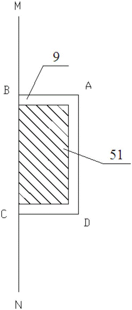
[0026] Such as Figure 1-2 As shown, a flat touch screen provided by the embodiment of the present invention includes a flexible circuit board 5 and a glass substrate 1, a lower optical adhesive layer 2, a lower conductive layer 3, a double-sided adhesive 4, an upper conductive layer 6, The upper optical adhesive layer 7 and the cover plate 8; the flexible circuit board 4 is electrically connected to the lower conductive layer 3 and the upper conductive layer 6 respectively and is arranged between them; an electronic coating is arranged between the upper optical adhesive layer 7 and the cover plate 8 layer 9, and the electronic coating 9 is located directly above the flexible circuit board 5.

[0027] Specifically, in this embodiment: the flexible circuit board 5 is bonded between the lower conductive layer 3 and the upper conductive layer 6 through the anisotropic conductive adhesive film, and the Bonding area (that is, the binding or sticking area) 51 is arranged on the flex...


PUM


Abstract

The invention provides a flat-touch screen. The flat-touch screen comprises a flexible circuit board 5, a glass substrate 1, a lower-layer optical adhesive layer 2, a lower-layer conducting layer 3, a double faced adhesive tape 4, an upper-layer conducting layer 6, an upper-layer optical adhesive layer 7 and a cover plate 8, wherein the glass substrate 1, the lower-layer optical adhesive layer 2, the lower-layer conducting layer 3, the double faced adhesive tape 4, the upper-layer conducting layer 6, the upper-layer optical adhesive layer 7 and the cover plate 8 are sequentially arranged in a stacked mode. The flexible circuit board 5 is electrically connected with the lower-layer conducting layer 3 and the upper-layer conducting layer 6 respectively and is arranged between the lower-layer conducting layer 3 and the upper-layer conducting layer 6. An electronic coating 9 is arranged between the upper-layer optical adhesive layer 7 and the cover plate 8 and used for isolating the upper-layer optical adhesive layer 7 from the cover plate 8, so that when the flexible circuit board 5 is connected with the lower-layer conducting layer 3 and the upper-layer conducting layer 6, the upper-layer optical adhesive layer 7 is only subjected to the tensile force of the upper-layer conducting layer 6, the phenomenon that air bubbles are produced due to excessive tensile force deformation between the upper-layer conducting layer 6 and the upper-layer optical adhesive layer 7 is avoided, and the electrical performance of the flat-touch screen is prevented from being influenced due to frequent pressing conducted on the flexible circuit board 5.

Description

technical field [0001] The invention relates to the technical field of touch screen manufacturing, in particular to a flat touch screen and a manufacturing method thereof. Background technique [0002] In the manufacturing process of the flat touch screen, it is necessary to use optical glue to bond the cover plate and the upper conductive layer, and connect the flexible circuit board to the conductive lines of the upper conductive layer. [0003] When pressing the cover directly above the flexible circuit board frequently, the following problems will occur: [0004] 1) Since the viscosity of the optical glue will pull the conductive line of the upper conductive layer, the connection between the flexible circuit board and the conductive line will be loosened, and the connection resistance at the connection will increase, resulting in poor electrical performance of the flat touch screen; [0005] 2) Since the flexible circuit board has a certain height, the optical adhesive ...

Claims


Application Information

Patent Timeline
IPC IPC(8): G06F3/041
Inventor 余盛海王立顺平冠军
Owner HUANGSHI RAECE TECH
Learn More