
Wear-resistant hydraulic hoist for controlling stable output of gate

A hydraulic hoist and stable output technology, applied in mechanical equipment, fluid pressure actuating devices, fluid pressure actuating system components, etc. Shortened life and other problems, to achieve the effect of preventing air bubbles, widening the scope of action, and improving practicability

Inactive Publication Date: 2018-07-24
SHENZHEN ANSIKE ELECTRONICS TECH CO LTD
View PDF5 Cites 4 Cited by
  • Summary
  • Abstract
  • Description
  • Claims
  • Application Information

AI Technical Summary

Problems solved by technology

[0003] During the operation of the hydraulic hoist, due to the reciprocating movement of the piston, the hydraulic oil in the hydraulic cylinder absorbs the kinetic energy of the piston, resulting in an increase in oil temperature. Since the hydraulic oil in the hydraulic cylinder is in a closed environment, the heating of the hydraulic oil will not only cause Expansion, but also produce air bubbles, affect the movement of the piston, resulting in unstable output of the hoist, not only that, when the hydraulic oil fills the inside of the hydraulic cylinder, the inner wall of the hydraulic cylinder is easy to absorb oil dirt, and the oil dirt is easy to adhere to various types Dust and impurities, when the piston moves to the oily position, it is easy to suck these dust and impurities into the hydraulic oil. With the increase of dust and impurities, these impurities are easy to wear the valves and other components inside the hoist, resulting in shortened service life of the equipment , thereby reducing the practicality of the existing hydraulic hoist

Method used


Image

  • Wear-resistant hydraulic hoist for controlling stable output of gate
  • Wear-resistant hydraulic hoist for controlling stable output of gate
  • Wear-resistant hydraulic hoist for controlling stable output of gate

Examples


Embodiment Construction

[0024] The present invention is described in further detail now in conjunction with accompanying drawing. These drawings are all simplified schematic diagrams, which only illustrate the basic structure of the present invention in a schematic manner, so they only show the configurations related to the present invention.

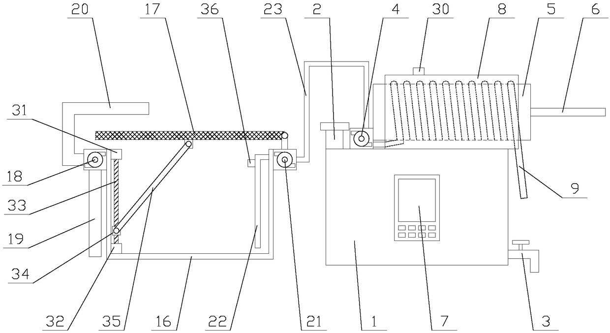
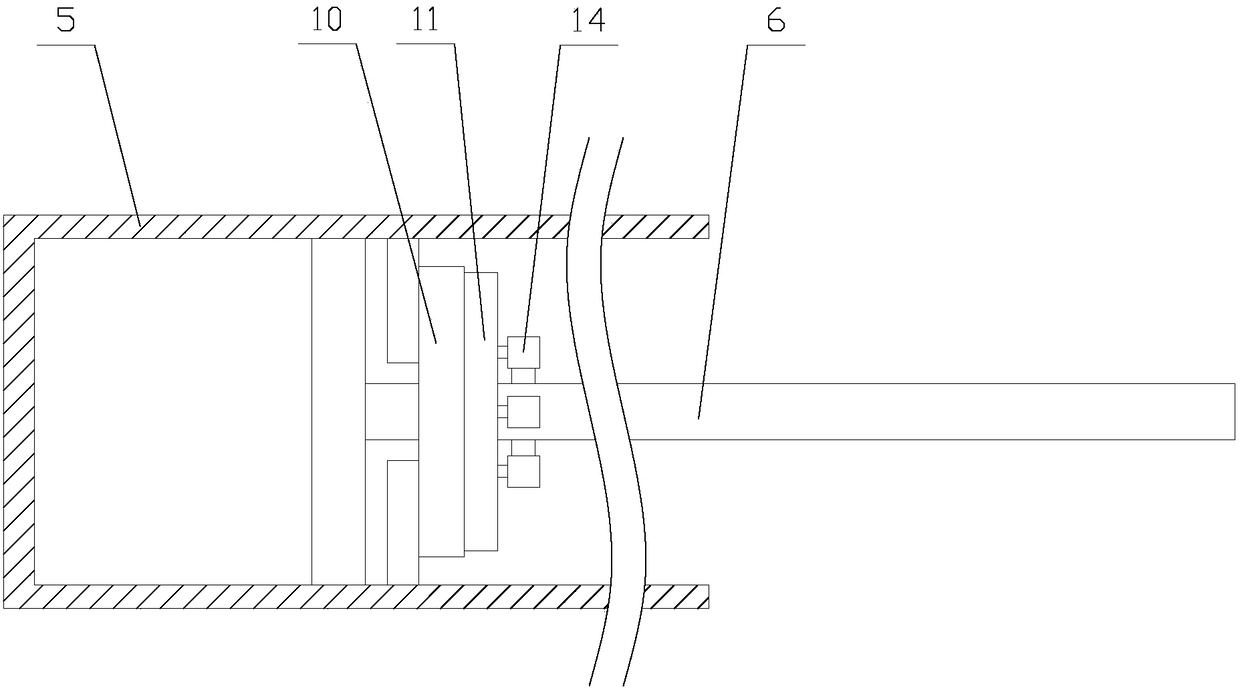
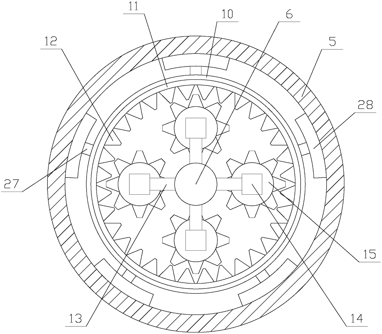
[0025] Such as figure 1 As shown, a hydraulic hoist for controlling the output of the gate is stable and wear-resistant, including a fuel tank 1, an oil injection pipe 2, an oil discharge pipe 3, a hydraulic pump 4, a hydraulic cylinder 5 and a piston 6, and the oil injection pipe 2 and The oil discharge pipe 3 is respectively located on the top of the fuel tank 1 and one side of the fuel tank 1, the oil injection pipe 2 and the oil discharge pipe 3 are connected with the fuel tank 1, the top of the oil injection pipe 2 is provided with a cover plate, and the oil discharge pipe 3 is provided with a There is a valve, the hydraulic pump 4 is fixed above the fue...


PUM


Abstract

The invention relates to a wear-resistant hydraulic hoist for controlling stable output of a gate. The wear-resistant hydraulic hoist comprises a fuel tank, a hydraulic pump, a hydraulic cylinder, a cleaning mechanism, a water supply mechanism, a heat conducting ring and a drain pipe, wherein the cleaning mechanism comprises a cleaning disc, a rotating ring, a plurality of rotating assemblies anda plurality of cleaning assemblies; the water supply mechanism comprises a water storage tank, a filter screen, a first water pump, a water suction pipe, a water injection pipe, a second water pump, awater conduit and a water guide tube. The wear-resistant hydraulic hoist for controlling stable output of the gate absorbs heat of the heat conducting ring conveniently by continuously inputting a water flow into the drain pipe through the water supply mechanism, so that the temperature of the hydraulic cylinder is reduced, hydraulic oil is prevented from being heated to expand to generate air bubbles, and stable output of the equipment is achieved. Furthermore, oil dirt on the inner wall of the hydraulic cylinder is absorbed through the cleaning mechanism and the condition that dust enters the hydraulic oil to lead to wear of equipment parts as the hydraulic cylinder is infected with dust is avoided, the equipment operates safely and reliably, and the practicality of the equipment is improved.

Description

technical field [0001] The invention relates to the field of hydraulic hoists, in particular to a hydraulic hoist for controlling gates with stable output and wear resistance. Background technique [0002] The hydraulic hoist is also called the gate hydraulic hoist. It refers to a hoist that uses the pressure of the liquid to transmit energy to control the opening or closing of the gate. It includes a hydraulic transmission system and an electro-hydraulic control system. It is composed of five parts: hydraulic pump, hydraulic valve, hydraulic cylinder, oil tank and accessories, electrical cabinet and operation table. [0003] During the operation of the hydraulic hoist, due to the reciprocating movement of the piston, the hydraulic oil in the hydraulic cylinder absorbs the kinetic energy of the piston, resulting in an increase in oil temperature. Since the hydraulic oil in the hydraulic cylinder is in a closed environment, the heating of the hydraulic oil will not only cause...

Claims


Application Information

Patent Timeline
IPC IPC(8): F15B21/08F15B21/04
CPCF15B21/08F15B21/041
Inventor 曹燕红
Owner SHENZHEN ANSIKE ELECTRONICS TECH CO LTD
Learn More