Packaging device for thin film capacitor production

A technology for film capacitors and packaging devices, which is applied in the direction of packaging capacitor devices, capacitors, capacitor manufacturing, etc., can solve the problems of manpower consumption and low efficiency, and achieve the effects of saving labor costs, good sealing effect, and high filling efficiency

Active Publication Date: 2021-08-06
ANHUI MASCOTOP ELECTRONICS
View PDF5 Cites 4 Cited by
  • Summary
  • Abstract
  • Description
  • Claims
  • Application Information

AI Technical Summary

Problems solved by technology

[0005] The purpose of the present invention is to solve the problem of labor-intensive and low efficiency in the prior art, and propose a packaging device for film capacitor production

Method used


Image

  • Packaging device for thin film capacitor production
  • Packaging device for thin film capacitor production
  • Packaging device for thin film capacitor production

Examples


Embodiment 1

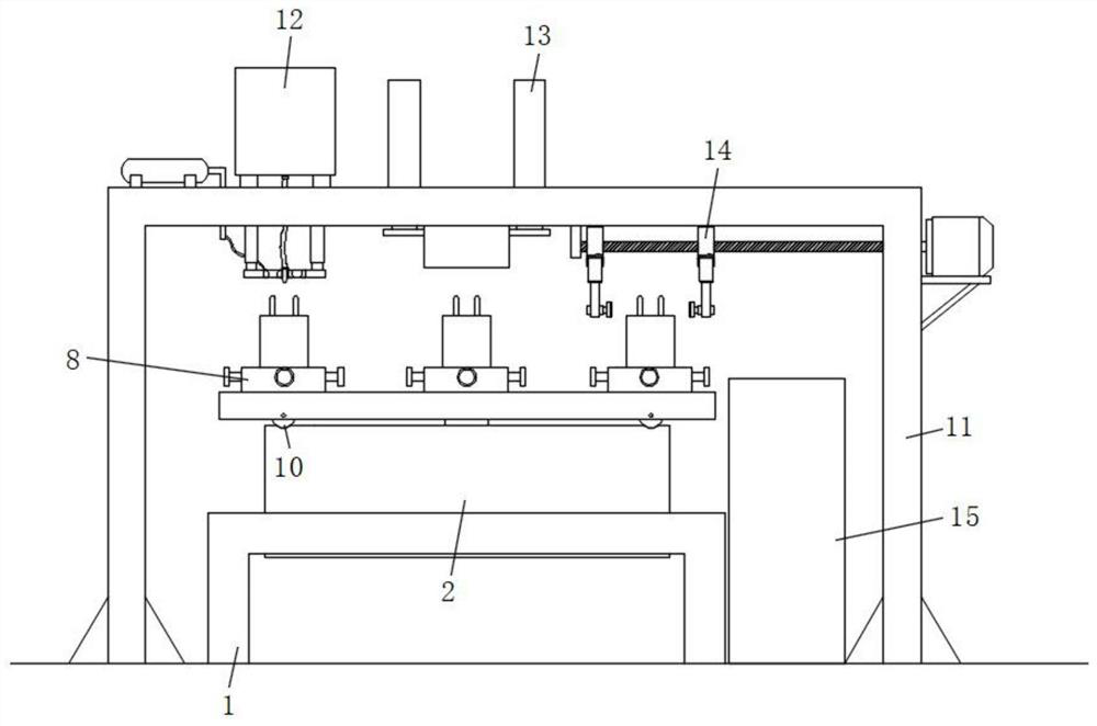
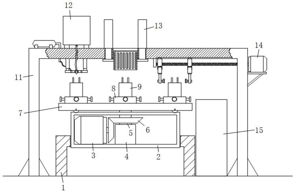
[0034] refer to Figure 1-6, a packaging device for film capacitor production, comprising a mounting frame-1, the top surface of the mounting frame-1 is provided with a mounting hole, the inner wall of the mounting hole is fixed with a drive box 2 by screws, and one side of the bottom surface of the drive box 2 passes through The screw is fixed with a servo motor 3, and the center of the inner bottom surface of the drive box 2 is also fixed with a stabilizing column 4, and the top surface of the stabilizing column 4 is connected with a mounting column 5 through a rolling bearing. Through the bevel gear set 6 rotation connection, the top of the mounting column 5 passes through the top surface of the drive box 2 and is fixedly connected with the rotating disc 7. The outer side of the top surface of the rotating disc 7 is fixed with a capacitor temporary fixing mechanism 8, and the capacitor temporary fixing mechanism 8 is placed There is a capacitor body 9, mounting frame 1 is p...

Embodiment 2

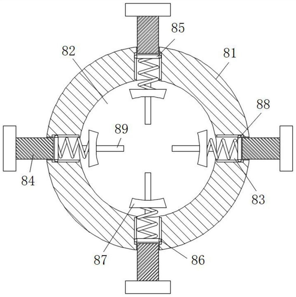
[0036] Such as figure 1 , 2 As shown in and 3, this embodiment is basically the same as Embodiment 1. Preferably, the capacitor temporary fixing mechanism 8 includes a fixed plate 81, the top surface of the fixed plate 81 is provided with a cylindrical groove 82, and the side wall of the cylindrical groove 82 is also provided with a threaded hole 83 , the inner wall of the threaded hole 83 is screwed with an adjusting rod 84, the inner wall of the threaded hole 83 is also slidably connected with a pressure plate 85, the both sides of the pressure plate 85 are fixed with a limit block 86, and the inner wall of the threaded hole 83 both sides is provided with a limit groove 1, And the limit block one 86 is all slidably connected in the limit groove one, and the side of the threaded hole 83 near the center of the cylindrical groove 82 is provided with an extrusion block 87, and an extrusion spring is fixedly connected between the extrusion block 87 and the pressing plate 85 88. ...

Embodiment 3

[0040] Such as figure 1 , 2 As shown in and 6, this embodiment is basically the same as Embodiment 1. Preferably, the unloading mechanism 14 includes a fixed block 141, and the fixed block 141 is fixed on the inner top surface of the mounting bracket 11 by screws, and one side of the fixed block 141 also rotates Connected with screw mandrel 142, the outer side of the upper end of mounting frame two 11 is fixedly connected with horizontal frame 143 by screws, and the top surface of horizontal frame 143 is fixedly connected with servo motor two 144 by screws, and the output end of servo motor two 144 is fixedly connected with screw mandrel 142. The outer wall of the rod 142 is also fixed with a mounting block 145 by threads, the top surface of the mounting block 145 is connected with the inner top surface of the mounting frame 11 by a limit block 2 146, and the bottom surface of the mounting block 145 is fixed with an electric telescopic rod by screws Three 147, the output ends...


PUM


Abstract

A packaging device for thin film capacitor production disclosed by the invention comprises a first mounting rack, wherein a mounting hole is formed in the top surface of the first mounting rack in a penetrating manner, a driving box body is fixedly connected to the inner wall of the mounting hole through a screw, a first servo motor is fixedly connected to one side of the inner bottom surface of the driving box body through a screw, a stabilizing column is further fixed to the center position of the inner bottom surface of the driving box body, a mounting column is rotationally connected to the top surface of the stabilizing column through a rolling bearing, the output end of the servo motor I is rotationally connected with the mounting column through a bevel gear set, the top end of the mounting column penetrates through the top surface of the driving box body and is fixedly connected with a rotating disc, a capacitor temporary fixing mechanism is fixed to the outer side of the top surface of the rotating disc, capacitor bodies are placed on the capacitor temporary fixing mechanisms, and a second mounting frame is erected on the outer side of the first mounting frame. The packaging device is reasonable in design, stable in device operation, high in filling efficiency and good in sealing effect during capacitor filling, and a certain guarantee is provided for high-quality preparation of capacitors.

Description

technical field [0001] The invention relates to the technical field of film capacitor production equipment, in particular to a packaging device for film capacitor production. Background technique [0002] Film capacitors use metal foil as an electrode, and plastic films such as polyethylene, polypropylene, polystyrene or polycarbonate are overlapped from both ends and wound into a cylindrical structure. In film capacitors Processing often needs to be packaged, which requires the use of packaging devices. [0003] After searching, the patent application number 201810453980.9 discloses a film capacitor potting device, which includes a conveying line and a preheating furnace, a glue filling machine, a vacuum defoaming machine and a curing furnace arranged sequentially along the conveying line. A capacitor fixture is installed on the conveyor line. [0004] The above-mentioned device performs vacuum defoaming treatment after the capacitor is filled with glue to ensure the seal...

Claims


Application Information

Patent Timeline
Patent Type & Authority Applications(China)
IPC IPC(8): H01G13/00
CPCH01G13/003
Inventor 王良国王军杨同彬
Owner ANHUI MASCOTOP ELECTRONICS
Why Eureka
Try Eureka