
Mutual capacitive fingerprint identification device, preparation method, display panel and display device

A fingerprint identification and display panel technology, which is applied in character and pattern recognition, acquisition/organization of fingerprints/palmprints, instruments, etc., can solve the problems of difficult identification of fingerprints and low sensitivity of fingerprint identification, and improve the ability of fingerprint identification , the effect of increasing the area

Active Publication Date: 2015-12-09
BOE TECH GRP CO LTD +1
View PDF6 Cites 17 Cited by
  • Summary
  • Abstract
  • Description
  • Claims
  • Application Information

AI Technical Summary

Problems solved by technology

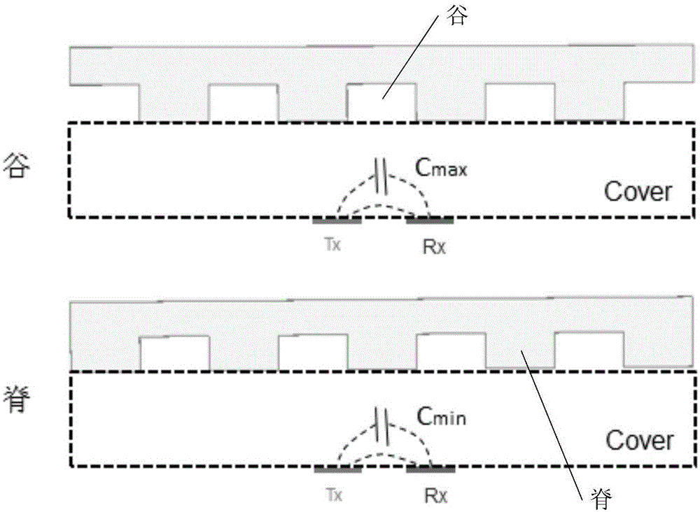
[0004] However, in the prior art, the difference ΔC between Cmax and Cmin is relatively small, resulting in low sensitivity of fingerprint identification, that is, it is not easy to distinguish the valleys and ridges of fingerprints.

Method used


Image

  • Mutual capacitive fingerprint identification device, preparation method, display panel and display device
  • Mutual capacitive fingerprint identification device, preparation method, display panel and display device
  • Mutual capacitive fingerprint identification device, preparation method, display panel and display device

Examples


Embodiment 1

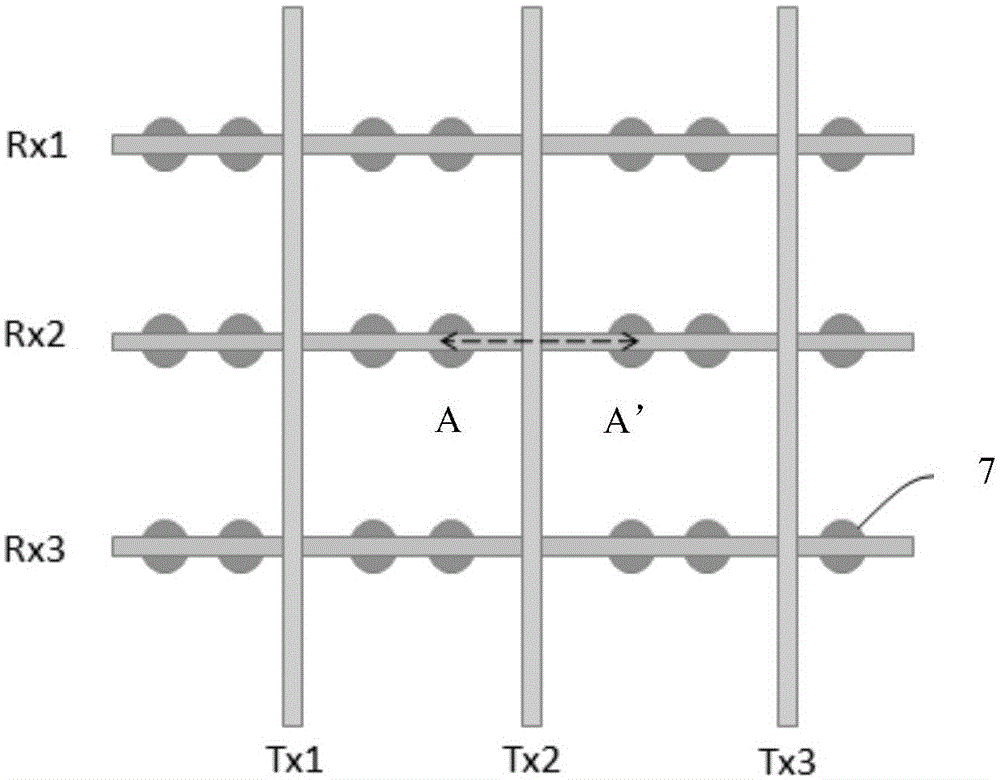
[0076] Embodiment one: see Figure 7 , the Tx line extends along the first direction, the Rx line extends along the second direction, the first direction and the second direction are perpendicular to each other, and each of the Tx lines includes three parts, namely the Tx main line, the first Tx branch line and the second Tx line Two Tx branch lines; wherein, the Tx main line is a Tx line extending along the first direction; the first Tx branch line is located on one side of the Tx main line and sandwiched between two adjacent Rx lines, and its length is less than that of the adjacent The distance between the Tx lines is half; the second Tx branch line is located on the other side of the Tx main line and sandwiched between two adjacent Rx lines, and the length is less than half the distance between adjacent Tx lines; specifically of, such as Figure 7 Partial enlarged view of the middle Tx line Figure 8 As shown, each of the Tx lines includes a Tx main line 8, a first Tx br...

Embodiment 2

[0077] Embodiment two: see Figure 9 The difference between the second embodiment and the first embodiment is that each Tx line has only a main line part and no branch line part.

Embodiment 3

[0078] Embodiment three: see Figure 10 , each Tx line is electrically connected at one end of two parallel wavy lines, and the other end extends along the first direction, and each Rx line is also electrically connected at one end of two parallel wavy lines, and the other end extends along the second direction, the The first direction and the second direction are perpendicular to each other.


PUM


Abstract

The invention provides a mutual capacitive fingerprint identification device, a preparation method, a display panel and a display device. The ability of fingerprint identification is improved. The mutual capacitive fingerprint identification device provided by the invention comprises a glass substrate, a glass cover, a drive electrode and a sensing electrode, wherein the drive electrode and the sensing electrode are located between the glass substrate and the glass cover. The drive electrode and / or the sensing electrode have / has a curved surface structure.

Description

technical field [0001] The invention relates to the field of display technology, in particular to a mutual-capacity fingerprint identification device and a preparation method, a display panel and a display device. Background technique [0002] Fingerprint is an invariable feature that is unique and distinguishable from others. It consists of a series of ridges and valleys on the skin surface of the fingertips. The details of these ridges and valleys usually include the bifurcation of ridges, the Details such as ends, arches, tent-like arches, left-handed, right-handed, spiral or double-handed, determine the uniqueness of the fingerprint pattern. Due to the wide application of computers and the development of pattern recognition theory, people have begun to study the automatic identification of fingerprints using computers. At present, countries all over the world are scrambling to research and develop practical fingerprint identification systems. [0003] The mutual capacit...

Claims


Application Information

Patent Timeline
Patent Type & Authority Applications(China)
IPC IPC(8): G06K9/00
CPCG06V40/1306G06F3/0446G06V40/1359G06F2203/04103
Inventor 李昌峰董学王海生陈小川王磊赵卫杰杨盛际丁小梁刘伟刘英明
Owner BOE TECH GRP CO LTD
Learn More