
Consequent pole brushless permanent magnet motor and electronic power-assisted steering system based on motor

A technology of electronic power steering and permanent magnet motor, which is applied in the direction of electric steering mechanism, magnetic circuit rotating parts, electromechanical devices, etc. It can solve the problems of high cost, large amount of permanent magnets, and environmental impact, so as to reduce the usage and reduce the System cost, small effect of magnetic field change

Active Publication Date: 2015-12-09
HUAZHONG UNIV OF SCI & TECH
View PDF6 Cites 5 Cited by
  • Summary
  • Abstract
  • Description
  • Claims
  • Application Information

AI Technical Summary

Problems solved by technology

[0009] Although the existing brushless permanent magnet motors used in electronic power steering systems can realize electronic commutation through external circuits, the brushes and commutators required by brushed DC motors are omitted, thereby avoiding commutation sparks and carbon brushes. However, since the N pole and S pole of the rotor magnetic field are composed of permanent magnets, the amount of permanent magnets is relatively large, especially the amount of rare earth permanent magnets is large, resulting in high cost and environmental impact.

Method used

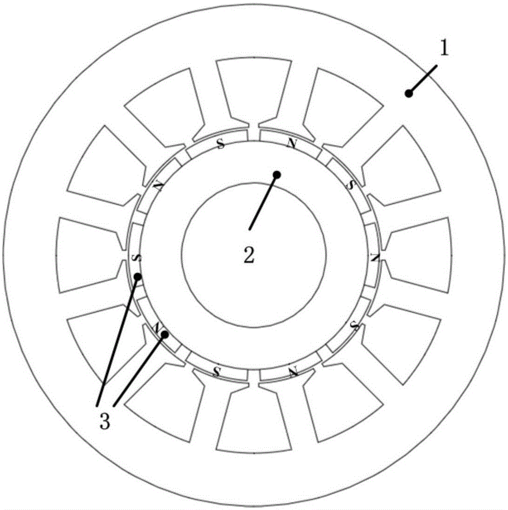
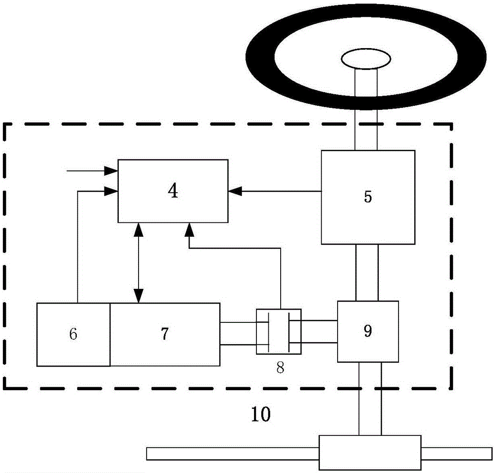
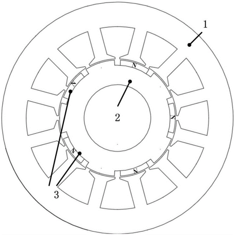

Image

  • Consequent pole brushless permanent magnet motor and electronic power-assisted steering system based on motor
  • Consequent pole brushless permanent magnet motor and electronic power-assisted steering system based on motor
  • Consequent pole brushless permanent magnet motor and electronic power-assisted steering system based on motor

Examples


Embodiment Construction

[0036] In order to make the object, technical solution and advantages of the present invention clearer, the present invention will be further described in detail below in conjunction with the accompanying drawings and embodiments. It should be understood that the specific embodiments described here are only used to explain the present invention, not to limit the present invention. In addition, the technical features involved in the various embodiments of the present invention described below can be combined with each other as long as they do not constitute a conflict with each other.

[0037] The device of the present invention is also applicable to various types of EPS such as steering shaft assist type, gear assist type, and rack assist type. In this embodiment, the steering shaft assist type EPS is used as an example for introduction.

[0038] like image 3 As shown, an alternating pole brushless permanent magnet motor constructed according to a preferred embodiment of the...


PUM


Abstract

The present invention discloses a consequent pole brushless permanent magnet motor used for an electronic power-assisted steering system. The motor comprises a stator iron core having a hollow cylinder shape, a rotor iron core having a hollow cylinder shape, and a plurality of magnetic steels, wherein the inner wall of the stator iron core is equipped with grooves, and the stator windings are placed in the corresponding stator grooves; the rotor iron core sleeves a central through hole of a stator cylinder coaxially, the outer surface of the rotor iron core is equipped with a plurality of grooves, and the number of the grooves is a half of the number of the motor operation magnetic field poles; the plurality of magnetic steels are placed in the grooves of the rotor iron core in a one-to-one correspondence manner, and the polarities of the magnetic steels in the adjacent grooves are same, so that the rotor magnetic steels only exist the single polarity and form the salient pole structures, and accordingly, the permanent magnet amount can be reduced, while an output torque of the motor can be kept. The present invention also discloses the corresponding electronic power-assisted steering system. According to the present invention, the rotor structure of the permanent magnet motor is optimized and improved, thereby reducing the permanent magnet amount of the motor rotor, and being able to save the position sensors of the power-assisted steering system.

Description

technical field [0001] The invention belongs to the technical field of power steering systems, and more particularly relates to a brushless permanent magnet motor used in a power steering system and an electronic power steering system based on the motor. Background technique [0002] The power steering system is an important part of modern automobiles. Its main function is that when the driver steers the steering wheel, the torque sensor detects the steering wheel's steering and the magnitude of the torque. The motor controller issues instructions to control the motor to output steering assist torque of corresponding magnitude and direction, thereby generating auxiliary power. [0003] At present, the power steering system of automobiles generally adopts the hydraulic power steering system. It can be said that after more than ten years of development, the hydraulic steering technology is relatively mature. However, from the development trend of the entire steering system, as...

Claims


Application Information

Patent Timeline
Patent Type & Authority Applications(China)
IPC IPC(8): H02K29/06H02K1/27B62D5/04
Inventor 曲荣海李大伟李健
Owner HUAZHONG UNIV OF SCI & TECH
Learn More