Roll mill

A roller mill and frame technology, applied in the field of roller mills, can solve the problems of complicated and time-consuming disassembly operations

Active Publication Date: 2015-12-09
F L SMIDTH & CO AS
View PDF8 Cites 2 Cited by
  • Summary
  • Abstract
  • Description
  • Claims
  • Application Information

AI Technical Summary

Problems solved by technology

This disassembly operation is complicated and time-consuming

Method used


Image

  • Roll mill
  • Roll mill
  • Roll mill

Examples


Embodiment Construction

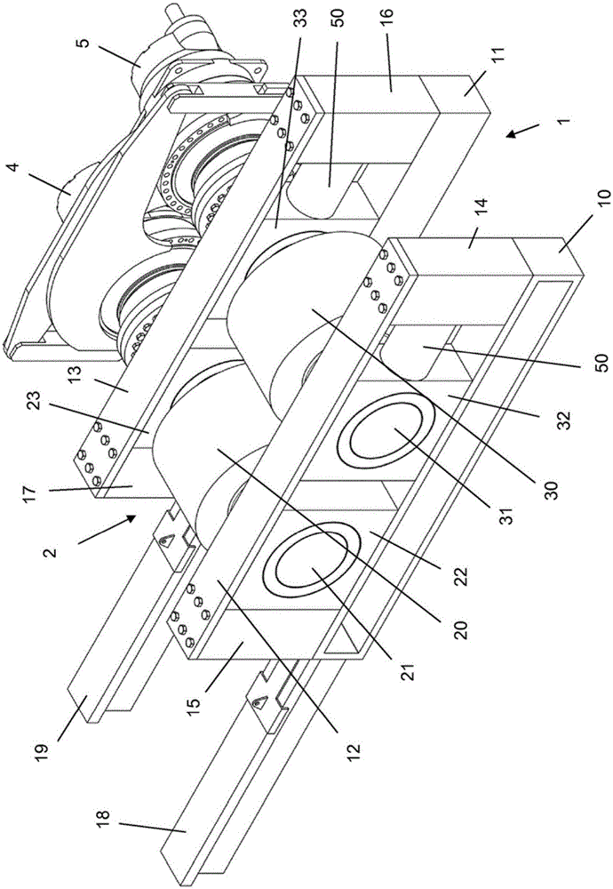
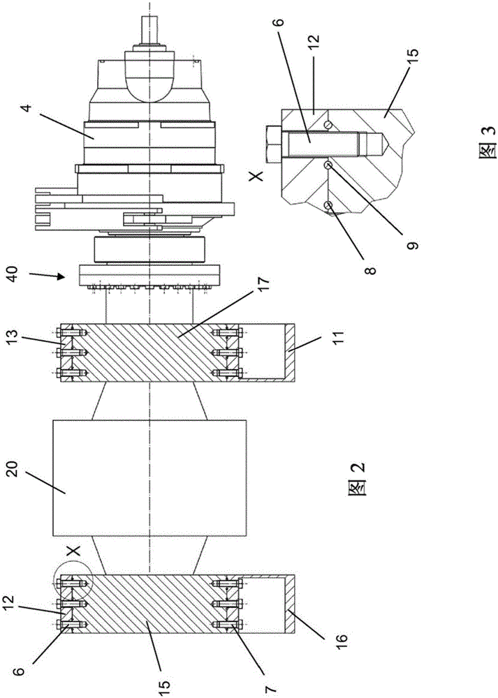
[0029] figure 1 The roller mill shown is a roller press or a material bed type roller mill. The roller mill has, for example, two roller units 2, 3, which are arranged in the frame 1 and in each type In each case, there is a grinding roller 20 or 30, wherein the grinding rollers are arranged opposite to each other, and in each case the grinding rollers are connected to driving devices 4, 5 for driving the grinding rollers in mutually opposite rotations. The frame is composed of two lower frame parts 10 and 11, two upper frame parts 12 and 13, and four compression beams 14-17. The grinding rollers 20, 30 are installed through the respective short shafts 21 or 31 in the respective jewel bearings 22, 23 or 32, 33, wherein the jewel bearings on the lower frame parts 10, 11 and the upper frame parts 12, 13 are slid And can be guided in a displaceable way.

[0030] In the illustrated exemplary embodiment, the roller unit 2 is installed as a fixed roller in the frame 1 and is supported...


PUM


Abstract

The invention relates to a roll mill with two roll units (2, 3) which are arranged in a machine frame (1) and each comprise a grinding roll (20, 30) rotatably mounted in two bearing blocks (22, 23, 32, 33), wherein: the two grinding rolls (20, 30) are disposed opposite one another and are each coupled to a drive (4, 5) for driving the grinding rolls in opposing directions; a force-application system (50) for generating a grinding force is provided between the machine frame (1) and at least one roll unit (3), the grinding force being transferred via the machine frame (1) and the bearing blocks (22, 23, 32, 33) to the grinding rolls (20, 30); and the machine frame (1) consists of a plurality of frame parts (10, 11, 12, 13), a detachable, interlocking connection having two connecting surfaces (15a, 12a) pressed against each other being provided between at least two interconnected frame parts and / or between at least one frame part and one of the bearing blocks in order to transfer the grinding force, at least one of the two connecting surfaces (15a, 12a) pressed against each other having a coating (8, 9) which generates a microscale interlocking connection.

Description

Technical field [0001] The present invention relates to a roller mill having two roller units arranged in a frame and in each case having a mill rotatably mounted in two jewel bearings Rollers, where two grinding rollers are arranged opposite to each other, and each grinding roller is connected to a driving device for driving the grinding rollers in mutually opposite rotations in each case. [0002] A force application system for generating grinding force is provided between the frame and at least one roller unit, wherein the grinding force is transmitted to the grinding roller via a jewel bearing and a frame composed of a plurality of frame parts. Here, in order to transmit the grinding force, a releasable interlocking connection of two connecting surfaces pressing against each other is provided between at least two interconnected frame parts and / or between the frame part and a jewel bearing. Background technique [0003] Since the grinding roller is worn during operation, the ro...

Claims


Application Information

Patent Timeline
Patent Type & Authority Applications(China)
IPC IPC(8): B02C4/28B30B15/04B02C4/02B30B3/04
CPCB02C4/02B02C4/28B30B3/04B30B15/04
Inventor 丹尼尔·弗雷里希路德维希·肯宁尼尔斯·赫斯特亚历山大·彼得斯
Owner F L SMIDTH & CO AS
Why Eureka
Try Eureka