
External grinding device for thin-walled part for motor

A technology for thin-walled parts and outer circle grinding, which is applied in the direction of grinding machines, abrasive belt grinders, grinding workpiece supports, etc. It can solve the problems of complex design, processing and manufacturing, unstable clamping force of workpieces, and inability to clamp workpieces, etc., to achieve Guaranteed machining accuracy, improved machining efficiency, and simple structure

Inactive Publication Date: 2015-11-11
CHONGQING SHANGZE ELECTROMECHANICAL
View PDF6 Cites 2 Cited by
  • Summary
  • Abstract
  • Description
  • Claims
  • Application Information

AI Technical Summary

Problems solved by technology

Liquid plastic is melted and boiled from polyvinyl chloride resin, dibutyl diformate, and calcium stearate. It has a certain consistency and viscosity, but when the gap between the workpiece and the fixture is large (greater than 0.05mm) , liquid plastics are prone to leakage, and the clamping force transmitted by the fixture to the workpiece is also very unstable, or the workpiece cannot be clamped. Therefore, the design, processing and manufacturing of the fixture itself are complicated, and the manufacturing cost is high, so it is difficult to be used for small batches of workpieces. processing

Method used


Image

  • External grinding device for thin-walled part for motor
  • External grinding device for thin-walled part for motor
  • External grinding device for thin-walled part for motor

Examples


Embodiment Construction

[0031] The present invention will be described in further detail below by means of specific embodiments:

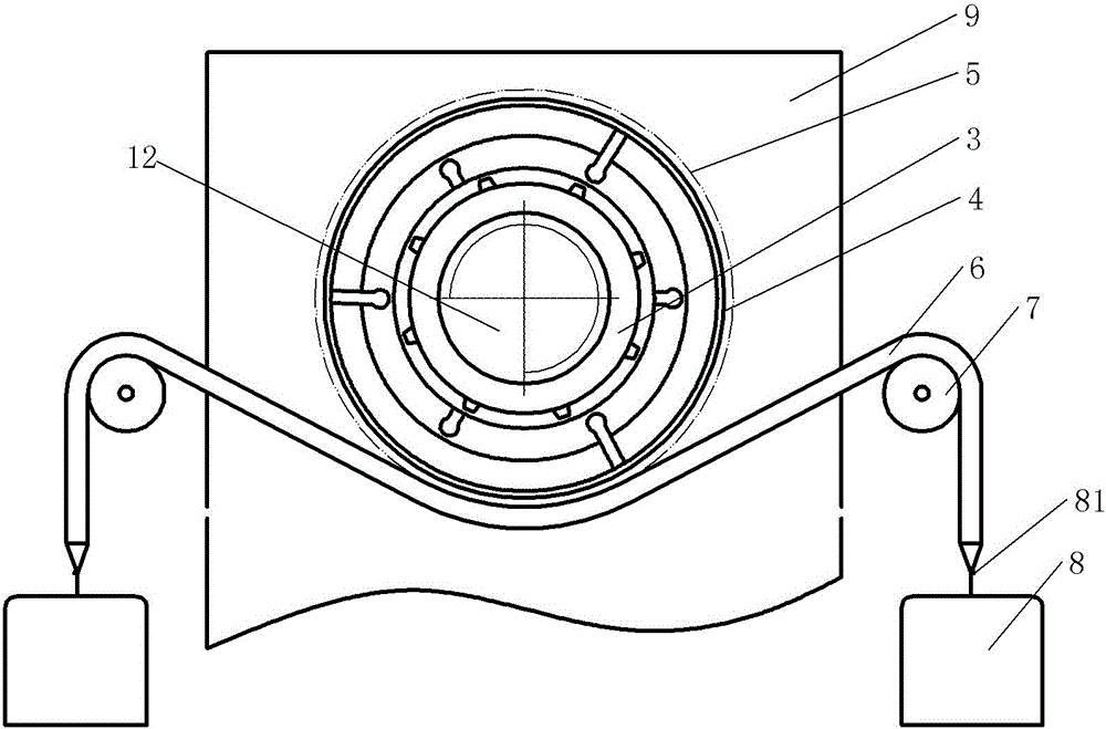
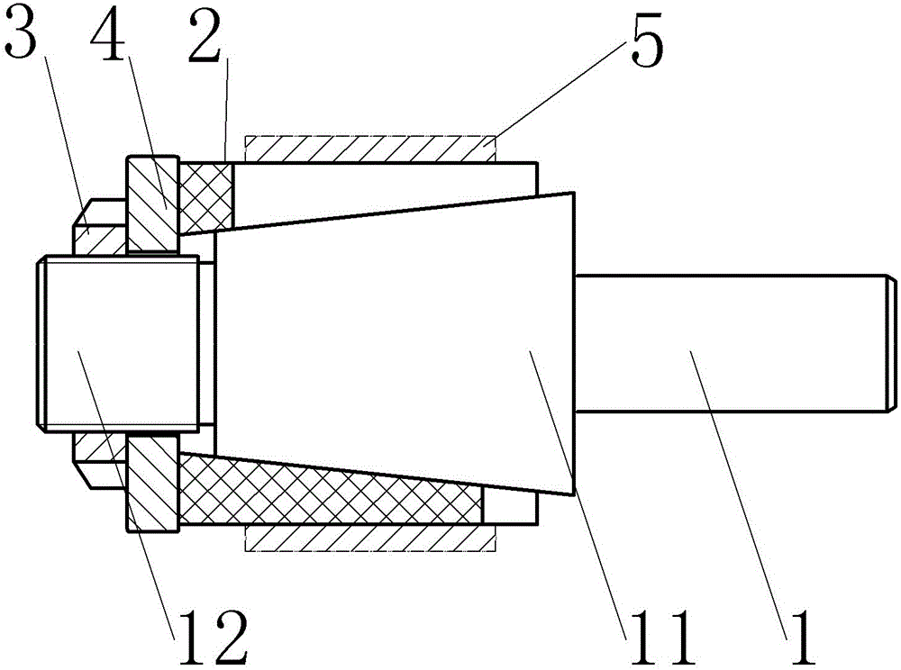
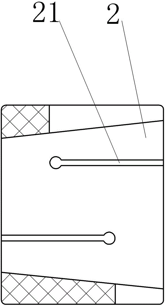
[0032] The reference signs in the drawings of the specification include: mandrel 1, expansion sleeve 2, compression nut 3, conical section 11, threaded section 12, pressure plate 4, workpiece 5, abrasive belt 6, support roller 7, counterweight 8, Hook 81, frame 9.

[0033] The embodiment is basically as attached figure 1 Shown:

[0034] The device for grinding the outer circle of thin-walled parts for motors includes a frame 9, a three-jaw chuck fixed on the frame 9, a spindle box for driving the three-jaw chuck, and an abrasive tool, and the abrasive tool includes two screws fixed on the frame 9 The support roller 7, two counterweights 8 and the abrasive belt 6 on the top, the abrasive belt 6 is located between the expansion sleeve 2 and the support roller 7, and the two ends of the abrasive belt 6 respectively bypass the support roller 7 and hang the counterweight 8; ...


PUM


Abstract

The invention discloses an external grinding device for a thin-walled part for a motor. The external grinding device comprises a rack, a clamp, a three-jaw chuck fixed to the rack, a spindle box driving the three-jaw chuck, and a grinding tool. The clamp comprises a mandrel, an expansion bushing, a pressing plate and a gland nut. The mandrel is provided with a threaded section and a conical section. The small-diameter end of the conical section is close to the threaded section. The gland nut is in threaded connection with the threaded section. The expansion bushing is a polyurethane expansion bushing. The inner working surface of the expansion bushing is arranged to be a taper hole. The conicity of the taper hole is matched with that of the conical section of the mandrel. The pressing plate is located between the gland nut and the expansion bushing. The pressing plate is annular. The inner diameter of the pressing plate is smaller than that of the expansion bushing and larger than the large diameter of the threaded section. The outer diameter of the pressing plate is larger than that of the expansion bushing. The grinding tool comprises two bearing rollers fixed to the rack, two counterweights and an abrasive belt. The abrasive belt is located between the expansion bushing and the bearing rollers. The two ends of the abrasive belt are wound around the bearing rollers and connected with the counterweights in a hanging mode. The external grinding device is easy to design and manufacture and capable of being applied to small-lot or single-piece production.

Description

technical field [0001] The invention relates to production equipment for processing motor parts, in particular to a device for grinding outer circles of thin-walled parts for motors. Background technique [0002] The motor refers to an electromagnetic device that realizes the conversion or transmission of electric energy according to the law of electromagnetic induction. It is represented by the letter M in the circuit. Its main function is to generate driving torque as a power source for electrical appliances or various machinery. There are motors on the motor. Lots of thin-walled parts. [0003] It is generally believed that in shell parts, sleeve parts, ring parts, disc parts, flat parts, and shaft parts, when the ratio of the part wall thickness to the inner diameter radius of curvature (or contour size) is less than 1:20, it is called thin-walled parts. The common characteristics of these parts are low rigidity and complex structure, which can easily cause error defor...

Claims


Application Information

Patent Timeline
IPC IPC(8): B24B21/02B24B21/16B24B41/06
CPCB24B21/02B24B21/16B24B41/067
Inventor 黄云凡
Owner CHONGQING SHANGZE ELECTROMECHANICAL
Learn More