Magnetic levitation of static or moving objects

A magnetic and permanent magnet technology, applied in the field of magnetic levitation systems, can solve problems such as being unsuitable for lifting objects magnetically

Inactive Publication Date: 2018-04-13
阿克斯帕克斯莱柏公司
View PDF7 Cites 0 Cited by
  • Summary
  • Abstract
  • Description
  • Claims
  • Application Information

AI Technical Summary

Problems solved by technology

[0008] Since the train cars have to be moved to generate magnetic lift in this manner, the system is not suitable for magnetically lifting objects while remaining in a stationary position

Method used


Image

  • Magnetic levitation of static or moving objects
  • Magnetic levitation of static or moving objects
  • Magnetic levitation of static or moving objects

Examples


Embodiment Construction

[0039]The invention will now be described in detail with reference to the accompanying drawings of some preferred embodiments shown in the accompanying drawings. In the following description, numerous specific details are set forth in order to provide a thorough understanding of the present invention. It will be apparent, however, to one skilled in the art that the present invention may be practiced without some or all of these specific details. In other instances, well known process steps and / or structures have not been described in detail in order not to unnecessarily obscure the present invention.

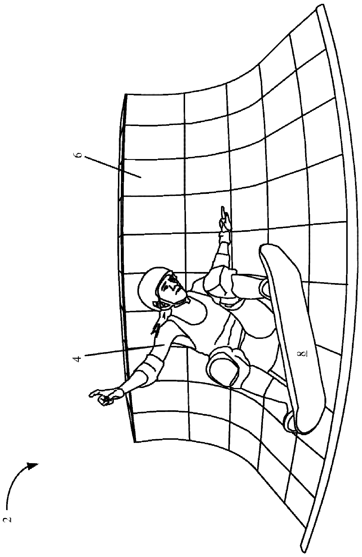
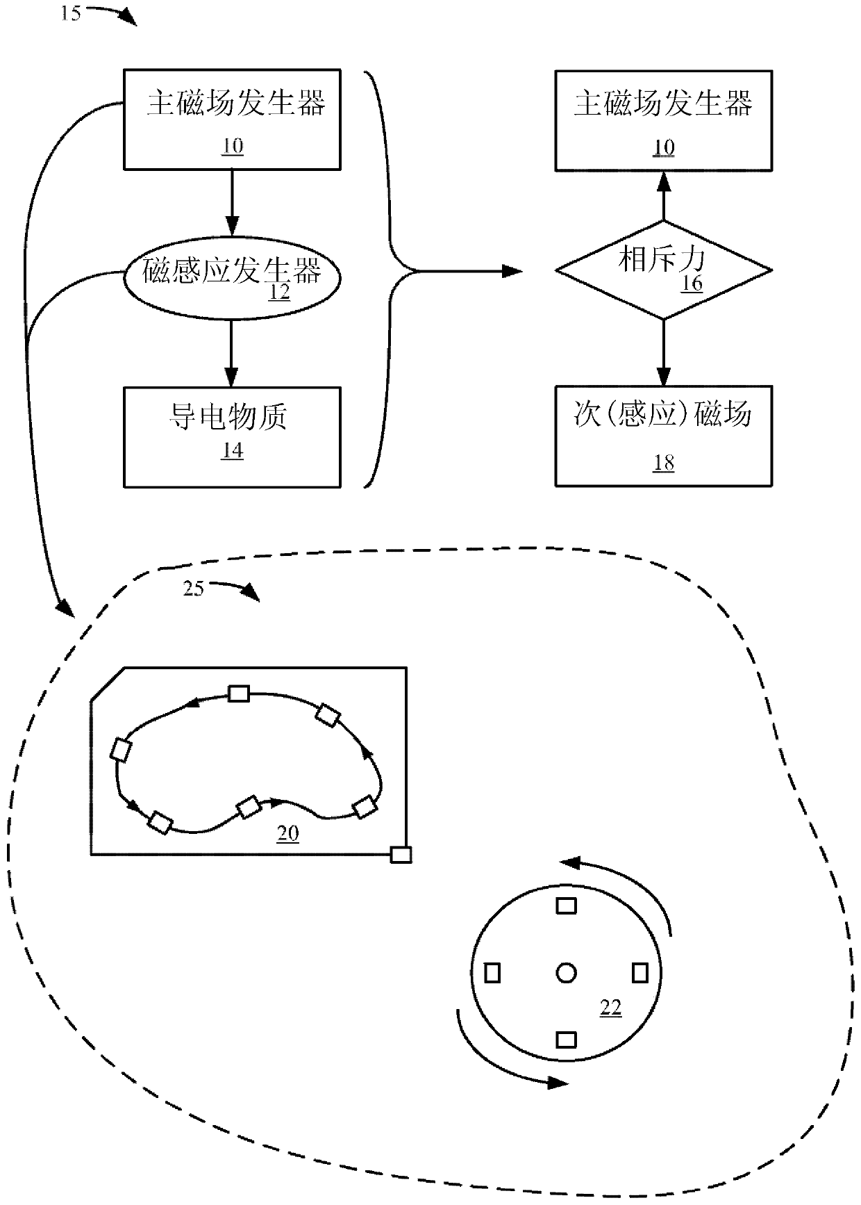
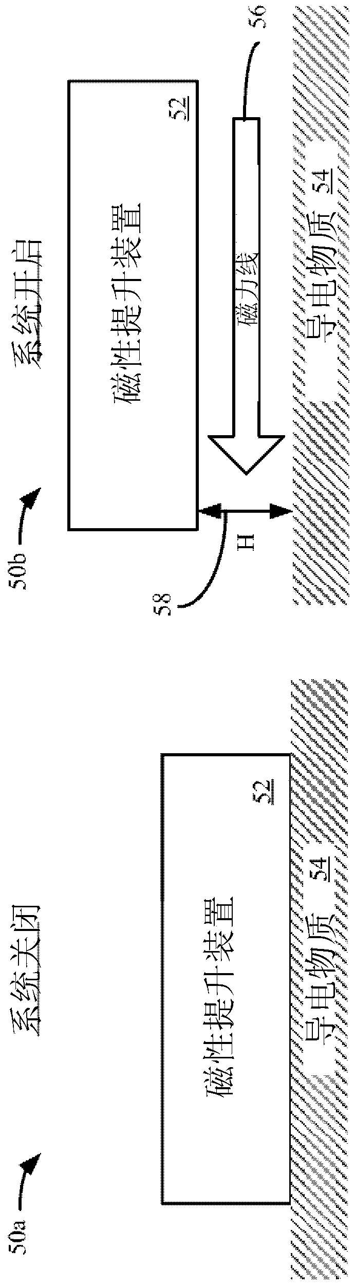
[0040] With reference to the figures and sections below, the magnetic lift system and its operation are described. especially for containing Figure 1-6 The first chapter of , entitled "Magnetic Lifting System, Components and Operation", describes some general examples of possible components of a magnetic lifting system, related elements and their arrangement, and the principl...


PUM


Abstract

A magnetic lifting device is described. The magnetic lift device can be configured to use a moving magnetic field to create an eddy current effect in the conductive substrate beneath the device to produce magnetic lift. In one embodiment, the moving magnetic field can be generated by a rotor driven by a motor with an array of permanent magnets. In operation, the rotor may accelerate from rest to above a threshold speed, which causes the magnetic lift to rise from the conductive substrate, levitate in place and move from one position to another in free flight. In free flight, a magnetic lift can be used to carry a payload, such as a person.

Description

[0001] CROSS-REFERENCE TO RELATED APPLICATIONS [0002] This patent application claims priority to pending US patent application US 14 / 069,359, filed October 15, 2013, and entitled "Magnetic Levitation of Static or Moving Objects," which claims 2013 under 35 U.S.C §119(e) Priority to US Provisional Patent Application Serial No. 61 / 799,695, filed March 15, entitled "Magnetic Levitation of Static or Moving Objects," both of which are incorporated by reference in their entirety for all purposes. technical field [0003] The present invention relates generally to magnetic levitation systems, and more particularly to static magnetic levitation by means of objects that generate induced magnetic fields. Background technique [0004] It is known that two permanent magnets will attract or repel each other at close range depending on how the poles of the magnets are aligned. When aligned with the gravity vector, the repulsive force can be used to counteract gravity and lift the objec...

Claims


Application Information

Patent Timeline
Patent Type & Authority Patents(China)
IPC IPC(8): B60L13/10B66C1/04B65G54/02
CPCA63C17/011A63C2203/12B60L13/04B60L15/002B60L15/20B60L2200/10B60L50/10B60L50/51H02N15/00Y02T10/64Y02T10/70Y02T10/7072Y02T10/72H02K7/09
Inventor D·格雷戈里·亨德森
Owner 阿克斯帕克斯莱柏公司
Why Eureka
Try Eureka