Stabilizer for magnetoresistive head and method of manufacture

a technology of magnetoresistive head and stabilizer, which is applied in the direction of magnetic bodies, instruments, record information storage, etc., can solve the problems of affecting the read sensor, adjacent bits, and the track width is so small, and it is difficult to avoid current leakage from the shield to the mr elemen

Inactive Publication Date: 2009-10-20
TDK CORPARATION
View PDF12 Cites 12 Cited by
  • Summary
  • Abstract
  • Description
  • Claims
  • Application Information

AI Technical Summary

Problems solved by technology

As a result, the track width is becoming so small that the magnetic field from the adjacent tracks, and not just the adjacent bits, will affect the read sensor.
As shield-to-shield spacing declines below about 40 nm, it is difficult to avoid current leakage from the shield to the MR element.
As a result of these layers 50, 51, the hard bias layer 52 is away from the free layer edge, which results in reduced stability due to the reduced hard bias field strength.
Further, because the sides of the hard bias layer 52 grow in an oblique manner, the magnetic field induced by the hard bias will have not have the same easy direction as the easy axis of the free layer.
This deviation between the free layer easy axis and the easy axis of the hard bias results in a less efficient hard bias.
However, this cannot be done with the presently used materials due to the coercivity requirements of the MR sensor.
However, the foregoing related art in-stack bias has various problems and disadvantages.
Thus, stability is reduced in at least those areas.
Thus, undesired magnetic fluctuation is generated.
Additionally, ion milling can damage the free layer edge.
As a result, the stabilizer layer is not fully pinned, and cannot provide the maximum stability.
In this aspect read head operating in CIP scheme (current-in-plane), various issues arise as the size of the sensor decreases.
When the electrode connected to the sensor is reduced in size overheating results and may potentially damage the sensor, as can be seen from FIG. 7(a).

Method used


Image

  • Stabilizer for magnetoresistive head and method of manufacture
  • Stabilizer for magnetoresistive head and method of manufacture
  • Stabilizer for magnetoresistive head and method of manufacture

Examples


Embodiment Construction

[0073]Referring now to the accompanying drawings, description will be given of preferred embodiments of the invention. Substantially similar elements of subsequent embodiments will not be repeated where those elements were already discussed with respect to a previous embodiment.

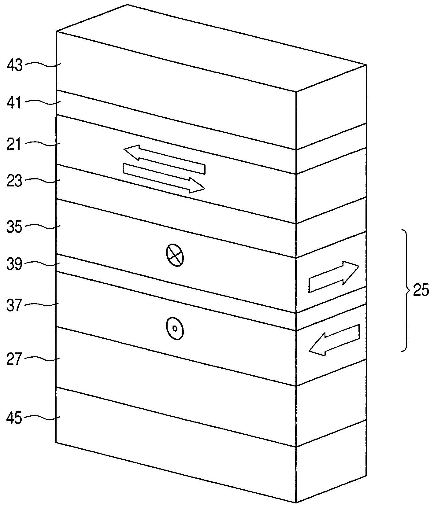
[0074]The present invention relates to a magnetoresistive sensor design for a reading head. The stabilizer of the reading head has a substantially small distance between the free layer and the stabilizer, as well as the high pinning field. Further, the sensing current substantially does not flow through the stabilizer.

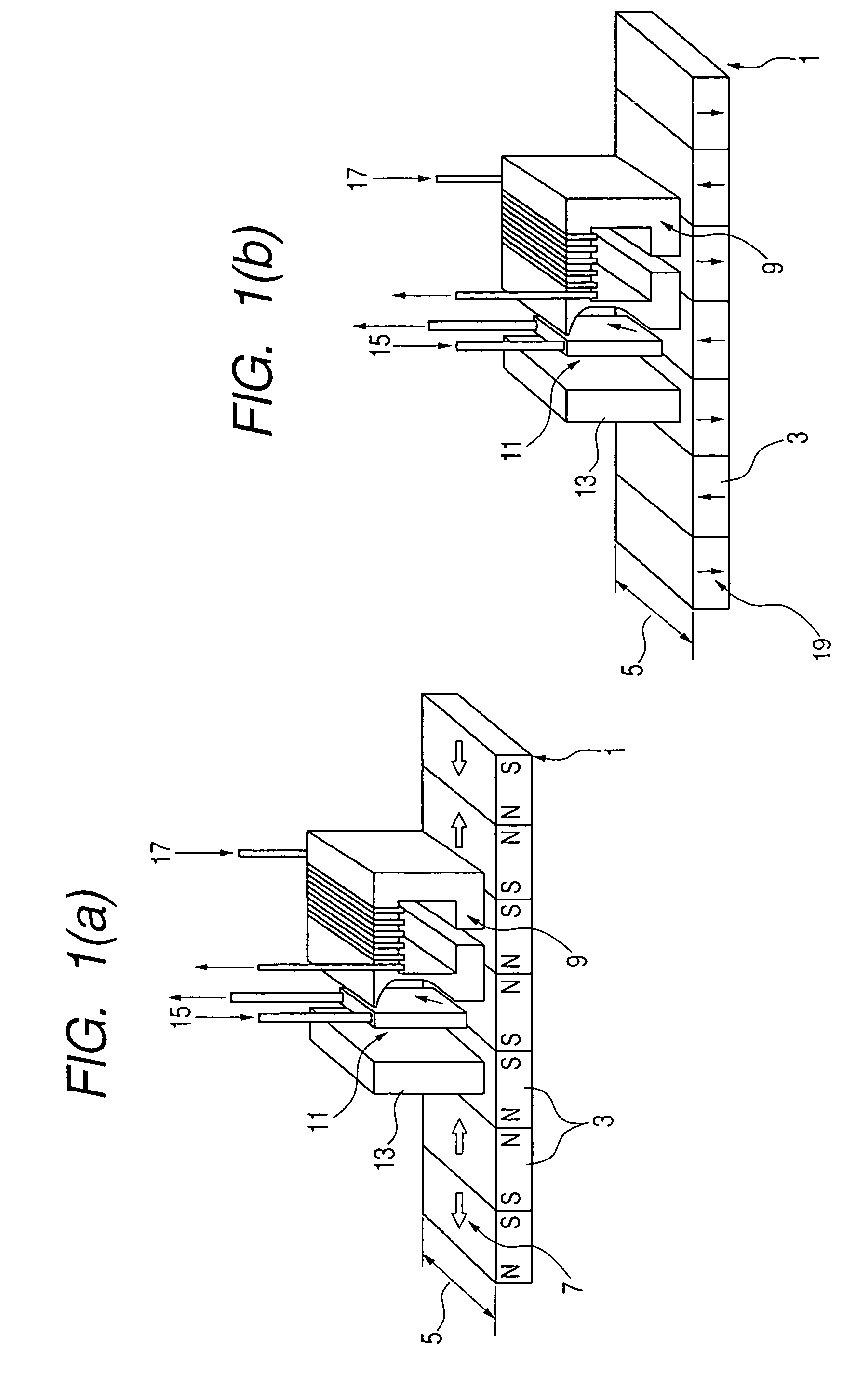
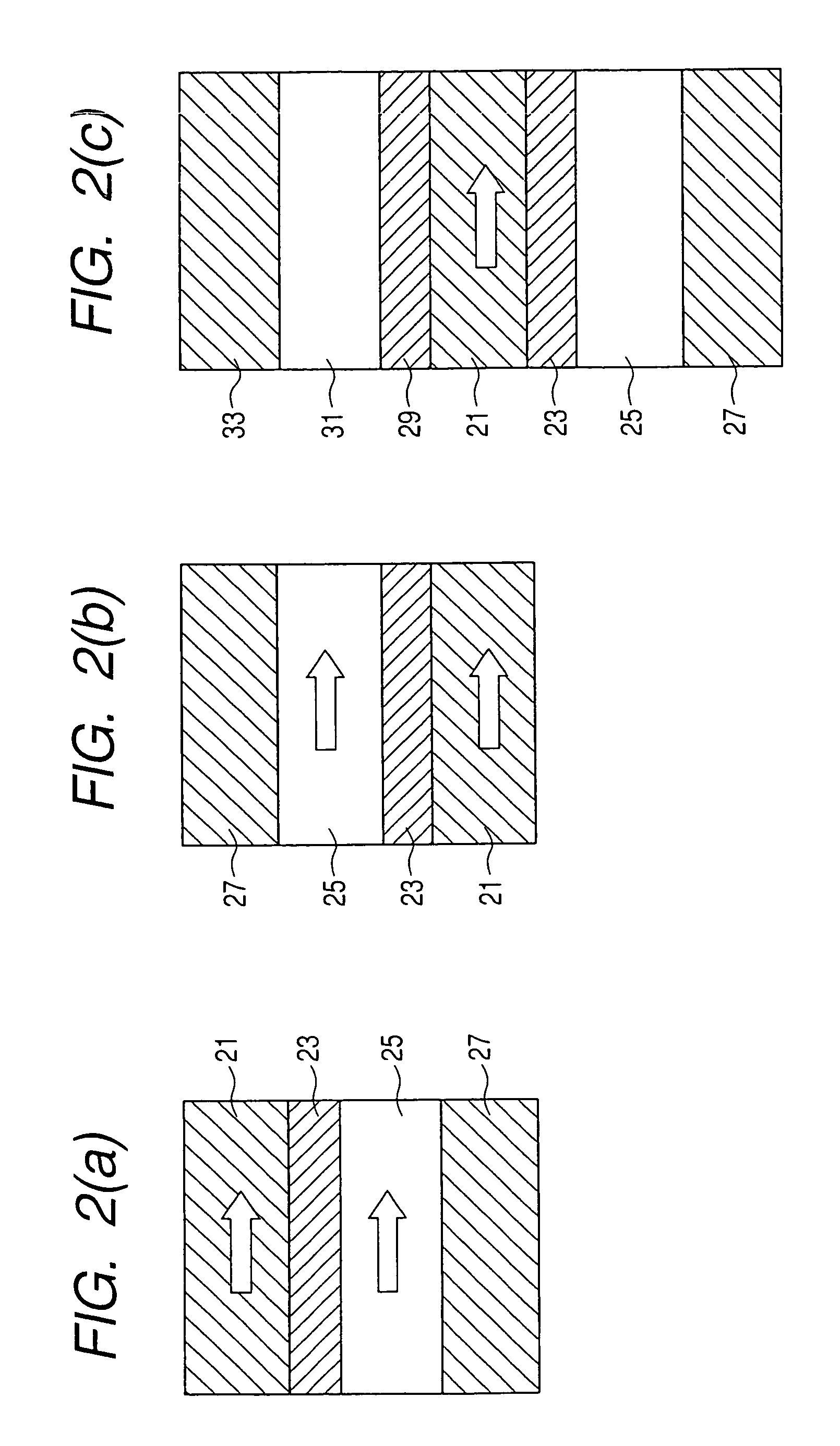
[0075]FIG. 9 illustrates a spin valve of a sensor for reading a magnetic medium according to an exemplary, non-limiting embodiment of the present invention. A spacer 101 is positioned between a free layer 100 and a pinned layer 102. As discussed above with respect to the related art, an external field is applied to the free layer 100 by a recording medium, such that the magnetization direction o...


PUM

PropertyMeasurementUnit
diameteraaaaaaaaaa
total thicknessaaaaaaaaaa

Abstract

A reader of a current-perpendicular-to-plane magnetoresistive head includes a spin valve with sensor having a stabilizer adjacent thereto, to substantially avoid magnetization distribution at the edge of the sensor due to vortex effect. At least one free layer is spaced apart from at least one pinned layer by a spacer. Above the free layer, a capping layer is provided. The stabilizer includes a pinned ferromagnetic layer adjacent to the free layer, and an antiferromagnetic layer positioned thereon. It becomes easy to provide an effective biasing using a variety of materials having different magnetic moments and thickness. Also problems related to sensor edge for small size will be overcome. A method of manufacturing the reader is also provided.

Description

TECHNICAL FIELD[0001]The present invention relates to a read element of a magnetoresistive (MR) head including a sensor having stabilizers on its sides, and a method of manufacture therefor. More specifically, the present invention relates to a spin valve of an MR read element having a pinned ferromagnetic layer next to the free layer.BACKGROUND ART[0002]In the related art magnetic recording technology such as hard disk drives, a head is equipped with a reader and a writer. The reader and writer have separate functions and operate independently of one another.[0003]FIGS. 1 (a) and (b) illustrate related art magnetic recording schemes. In FIG. 1(a), a recording medium 1 having a plurality of bits 3 and a track width 5 has a magnetization parallel to the plane of the recording media. As a result, a magnetic flux is generated at the boundaries between the bits 3. This is also commonly referred to as “longitudinal magnetic recording media” (LMR).[0004]Information is written to the recor...

Claims


Application Information

Patent Timeline
Patent Type & Authority Patents(United States)
IPC IPC(8): G11B5/127G11B5/39
CPCB82Y25/00B82Y40/00G01R33/093G11B5/3906G11B5/3932H01L43/12H01F10/3272H01F41/302H01L43/08G11B5/398H01F10/3254H01F10/3259H10N50/10H10N50/01
Inventor SBIAA, RACHIDMORITA, HARUYUKI
Owner TDK CORPARATION
Why Eureka
Try Eureka