Fertilizer applicator

A technology of a fertilizer applicator and a main frame, applied in the field of fertilizer applicators, can solve the problems of reduced crop yield, uneven fertilizer application, increased labor cost, etc.

Inactive Publication Date: 2015-12-16
广东德苑环境建设有限公司
View PDF6 Cites 3 Cited by
  • Summary
  • Abstract
  • Description
  • Claims
  • Application Information

AI Technical Summary

Problems solved by technology

[0002] With the continuous upgrading of agricultural industrialization, some shortcomings of traditional agriculture are gradually exposed. The increase in labor costs has adversely affected production. Improving agricultural production methods has become a symbol of modern agriculture. In agricultural production, fertiliz

Method used


Image

  • Fertilizer applicator
  • Fertilizer applicator
  • Fertilizer applicator

Examples


Embodiment 1

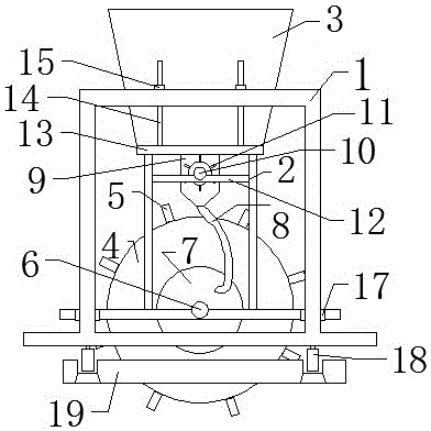
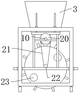
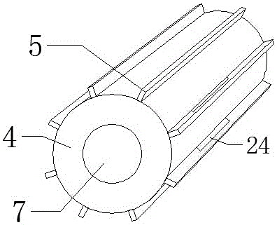
[0017] Embodiment 1: as figure 1 , figure 2 , image 3 , Figure 4 As shown, a fertilizer applicator includes a main frame 1, a sub-frame 2 arranged inside the main frame 1, and a slide rail 19 provided at the bottom of the main frame 1. The bottom of the sub-frame 2 is rectangular, and the length of the front side and the length of the rear side are at both ends. The clips 17 are respectively provided, and the clips 17 are fastened on the column of the main frame 1, and the rotation shaft 6 is set at the middle position between the front side length and the back side length of the bottom of the sub-frame 2, and the rotation shaft 6 passes through the baffle plate 25 set in the drum 4 and behind the drum 4 On the end face, the surface of the drum 4 is evenly equipped with a water-beating plate 5, and the water-beating plate 5 is provided with a water inlet 24 near the center of the drum 4, and the front end of the drum 4 is provided with a feeding opening 7, and the rear en...


PUM


Abstract

The invention relates to a fertilizer applicator which comprises a main frame, an auxiliary frame and a sliding rail. The auxiliary frame is arranged in the main frame, and the sliding rail is arranged at the bottom of the main frame. The bottom of the auxiliary frame is rectangular, clips are arranged, a rotary shaft is arranged at the bottom of the auxiliary frame and penetrates through a baffle arranged in a roller and the rear end face of the roller, flutter boards are evenly arranged on the surface of the roller, and water inlets are formed in the positions, close to the center of the roller, of the flutter boards. A small clamping wheel is arranged on the rear end face of the rotary shaft, a fertilizer cutting box is arranged below a feeding hopper, a center shaft is arranged in the fertilizer cutting box, blocking sheets are evenly arranged on the surface of the center shaft, a large clamping wheel is arranged on the rear end face of the center shaft, and the top of the auxiliary frame extends towards the front edge and the rear edge to be provided with a platform. Bolts are arranged on the platform and penetrate through the top of the main frame to be buckled with nuts. Due to the design of the fertilizer cutting box, fertilizer dividing is more even, and fertilizer can be fully dissolved in irrigation water; due to the design of the roller, the roller operates along with movement of water flow, manual operation is not needed, and safety and environment friendliness are achieved; due to the design of the fertilizer cutting box, the fertilizer is evenly cut out, and full dissolving is guaranteed.

Description

technical field [0001] The invention relates to a fertilizer applicator used in agricultural production, which is easy to operate, completely depends on water flow movement and does not need manual operation, and can accurately feed materials to facilitate people to spread fertilizer on the land. Background technique [0002] With the continuous upgrading of agricultural industrialization, some shortcomings of traditional agriculture are gradually exposed. The increase in labor costs has adversely affected production. Improving agricultural production methods has become a symbol of modern agriculture. In agricultural production, fertilizers are mixed into irrigation water for irrigation. Fertilization reduces labor intensity and production costs, and improves agricultural production levels. Because chemical fertilizers are in the form of mud, they cannot be fully dissolved when stirred into water, resulting in uneven application of fertilizers and reduced crop yields. Conte...

Claims


Application Information

Patent Timeline
IPC IPC(8): A01C23/04
Inventor 尹启礼
Owner 广东德苑环境建设有限公司
Why Eureka
Try Eureka