Bottom flow shearing and thickening device and method for thickener

A thickener and machine bottom technology, applied in the thickener field, can solve the problems of low underflow concentration, inability to discharge, motor shutdown, etc., to achieve obvious economic benefits, reduce power consumption, and overcome the effects of low concentration efficiency

Active Publication Date: 2015-12-16
SHANDONG UNIV OF SCI & TECH
View PDF4 Cites 2 Cited by
  • Summary
  • Abstract
  • Description
  • Claims
  • Application Information

AI Technical Summary

Problems solved by technology

The traditional thickener scrapes the concentrated tailings to the bottom discharge well for discharge through the rake frame. The rake frame can stabilize the bottom flow and prevent blockage. However, when the concentration of the bottom slurry is too high, the running resistance of the rake frame will increase. In extreme cases, the motor will automatically stop and a rake accident will occur
In response to this problem, researchers and related companies have developed a rake-free paste thickener. This type of thickener has no power structures such as rake racks inside, and only controls the discharge of the underflow through the bottom discharge pump, but the rake-free paste thickener has no effect on The control of underflow is not ideal. In the case of adding flocculant, a part of free water will be wrapped inside the floc after the floc settles at the bottom of the thickener. When the floc is in the compression zone at the bottom of the thickener, this part of water cannot be discharged, so will result in low underflow concentrations

Method used


Image

  • Bottom flow shearing and thickening device and method for thickener
  • Bottom flow shearing and thickening device and method for thickener
  • Bottom flow shearing and thickening device and method for thickener

Examples


Embodiment Construction

[0021] The technical solution of the present invention will be described below in conjunction with the accompanying drawings and specific embodiments.

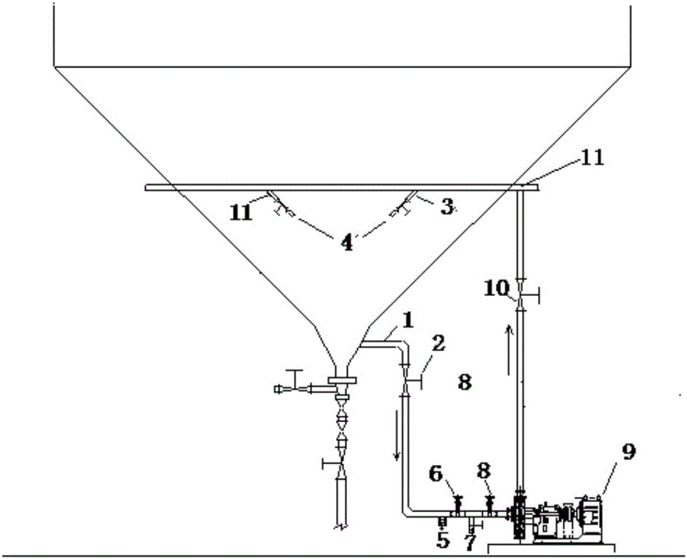
[0022] Such as figure 1 As shown, the underflow shear thickening device of the thickener of the present invention is connected to a suction pipe 1 on the bottom side of the thickener cone, and a circle of feeding pipes is arranged around the cone in the middle of the thickener cone 11. The feed pipe 11 surrounds the cone and connects with the suction pipe 1 through the circulation pump 9; the feed pipe 11 is provided with several symmetrical spraying branch pipes 3, and the spraying branch pipe 3 is equipped with a branch valve 4. The spraying branch pipe 3 enters perpendicular to the side wall of the cone; the main valve 2, the sewage valve 5, the sewage cleaning and recoil water valve 6 of the suction pipe, the sewage and recoil water inlet 7 and the water supply pipe are successively arranged on the suction pipe 1 Feed pip...


PUM

PropertyMeasurementUnit
strengthaaaaaaaaaa

Abstract

The invention discloses a bottom flow shearing and thickening device and method for a thickener. A sucking pipe is communicated with one side of the bottom of a thickener cone, a feeding pipe is arranged in the middle of the thickener cone in the mode of surrounding the cone by a round, after surrounding the cone by one round, the feeding pipe is connected with the sucking pipe through a circulating pump, and multiple symmetrical spraying branches with valves are arranged on the feeding pipe and enter in the mode of being perpendicular to the side wall of the cone. The sucking pipe is sequentially provided with a main valve, a blowdown valve, a sucking pipe decontaminating backwash water valve, a decontaminating backwash water inlet and a feeding pipe decontaminating backwash water valve, and a main valve is arranged on the feeding pipe. An ore pulp self-circulation mode is adopted to evenly mix ore pulp at the bottom of the thickener so as to stably discharge bottom flow; floc structures are destroyed by means of shearing force in the ore pulp circulation process, water contained in the floc structures is released, the concentration efficiency is improved, and the purpose of increasing pulp concentration is achieved finally.

Description

technical field [0001] This invention relates to thickeners. Background technique [0002] Thickener is a solid-liquid separation equipment for processing ore pulp to obtain high-concentration tailings in mine production. Thickener is also widely used in metallurgy, materials, papermaking and other industries. The traditional thickener scrapes the concentrated tailings to the bottom discharge well for discharge through the rake frame. The rake frame can stabilize the bottom flow and prevent blockage. However, when the concentration of the bottom slurry is too high, the running resistance of the rake frame will increase. In extreme cases, the motor will automatically stop and a rake accident will occur. In response to this problem, researchers and related companies have developed a rake-free paste thickener. This type of thickener has no power structures such as rake racks inside, and only controls the discharge of the underflow through the bottom discharge pump, but the rak...

Claims


Application Information

Patent Timeline
Patent Type & Authority Applications(China)
IPC IPC(8): B01D21/02
Inventor 吕宪俊曹晓强李琳胡术刚吴蓬
Owner SHANDONG UNIV OF SCI & TECH
Why Eureka
Try Eureka