Workpiece attaching machine

A technology for placement machines and parts, which is applied in the field of placement machines, can solve the problems of limiting the types of operating parts, etc., and achieve the effects of improving the combination of finished products, improving precision, and increasing utilization rate

Inactive Publication Date: 2015-12-16
舒建文
View PDF10 Cites 3 Cited by
  • Summary
  • Abstract
  • Description
  • Claims
  • Application Information

AI Technical Summary

Problems solved by technology

Traditional placement machines can only use suction pens (or suction nozzles) to pick up small and light parts, but cannot pick up larger and heavy parts, which limits the types of working parts

Method used


Image

  • Workpiece attaching machine
  • Workpiece attaching machine
  • Workpiece attaching machine

Examples


Embodiment Construction

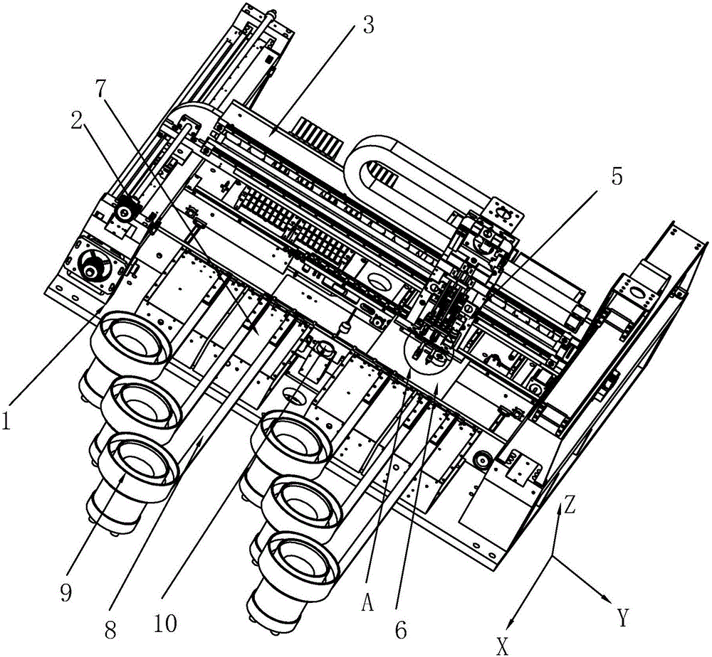
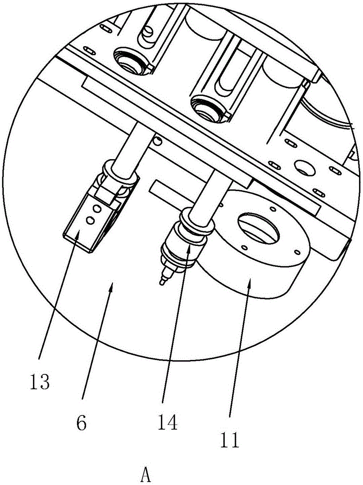
[0040] refer to Figure 1 to Figure 4 A specific embodiment of a mounting machine of the present invention will be further described.

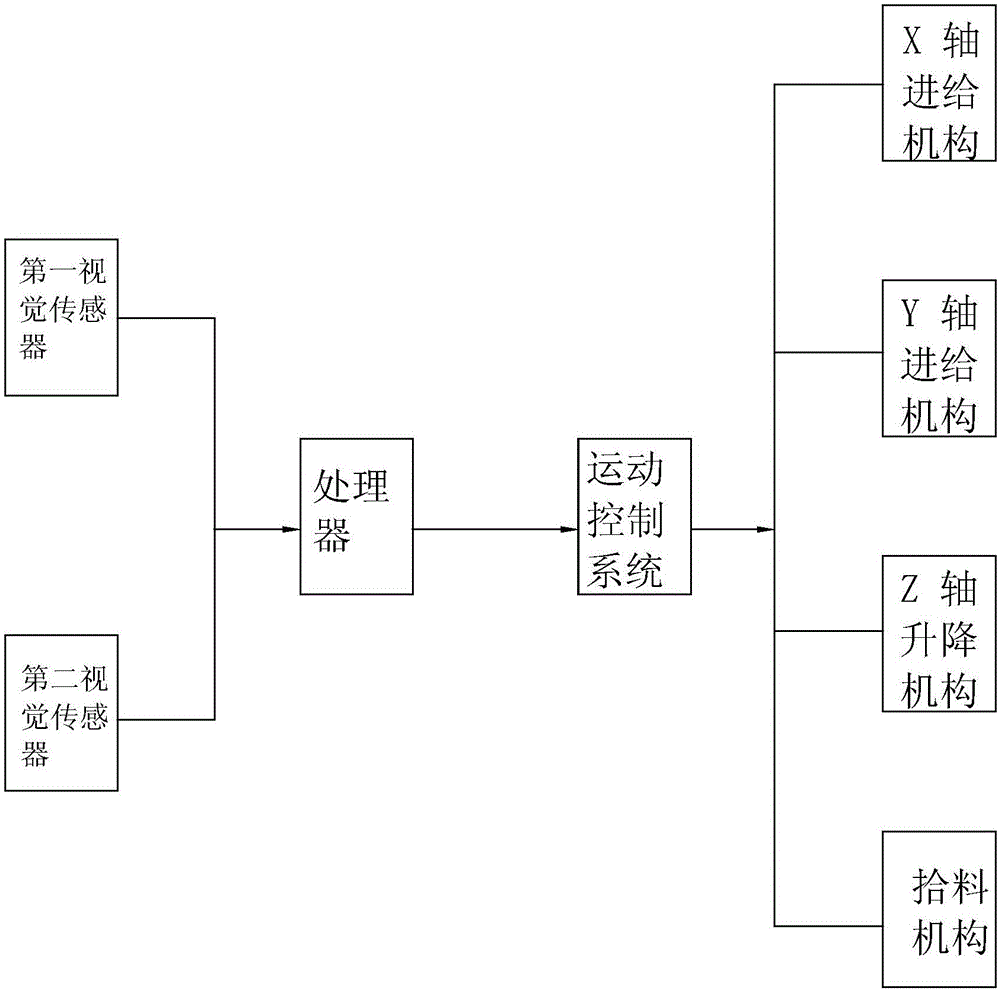
[0041] refer to Figure 1 to Figure 4 A placement machine shown includes a workbench 1 and a motion control system all arranged on the workbench 1, an X-axis feed mechanism 2, a Y-axis feed mechanism 3, and a Z-axis lift mechanism (the The X-axis feed mechanism 2, the Y-axis feed mechanism 3, and the Z-axis lifting mechanism are all described in detail in the invention patent with the application number 201410444923.6. The applicant does not explain the X-axis feed mechanism 2 and the Y-axis feed mechanism one by one. Concrete structure of feeding mechanism 3, Z-axis lifting mechanism) and material picking mechanism 5.

[0042] refer to figure 1 As shown, the pick-up mechanism 5 can move forward and backward in the X-axis direction under the action of the X-axis feed mechanism 2, and can move left and right in the Y-axis direction under the...


PUM


Abstract

The invention discloses a workpiece attaching machine which comprises a worktable, a movement control system, an X-axis feeding mechanism, a Y-axis feeding mechanism, a Z-axis lifting mechanism and a material picking mechanism. The material picking mechanism freely moves on the worktable in the three-dimensional direction through the joint action of the X-axis feeding mechanism, the Y-axis feeding mechanism and the Z-axis lifting mechanism. The movement control system is electrically connected with the X-axis feeding mechanism, the Y-axis feeding mechanism, the Z-axis lifting mechanism and the material picking mechanism. The worktable comprises an assembly area and a feeding area. A plurality of feeding rails used for conveying parts are distributed on the feeding area at intervals, and the end, outside the worktable, of each feeding rail is connected with one vibration plate. A first vision sensor is arranged on the feeding area, and a second vision sensor is arranged on the assembly area. The workpiece attaching machine further comprises a processor, and the first vision sensor and the second vision sensor are both electrically connected with the movement control system through the processor.

Description

technical field [0001] The invention relates to the field of assembly, and more specifically relates to a mounting machine. Background technique [0002] The Chinese utility model patent document with the application number 201320853686.X discloses a turntable mechanism, which includes a bottom plate, a calibration mechanism, a suction nozzle mechanism, a carrier mechanism and a rotating mechanism, and the product and multiple parts are placed on the carrier mechanism at the same time The calibration mechanism includes a light source, a light source bracket, a CCD, a CCD installation angle, a CCD installation block and a CCD adjustment block, the light source bracket is installed on the surface of the base plate, and a light source is installed on it; the CCD installation block is installed on the back of the base plate, The CCD is installed on the CCD installation angle, and the CCD is also fixed on the CCD adjustment block. The CCD adjustment block can adjust the position ...

Claims


Application Information

Patent Timeline
Patent Type & Authority Applications(China)
IPC IPC(8): B23P19/04
CPCB23P19/001B23P19/007B23P19/04
Inventor 舒建文
Owner 舒建文
Why Eureka
Try Eureka