Control method for injection molding machine

A technology of injection molding and control method, which is applied to household components, household appliances, other household appliances, etc., can solve the problems of poor maintainability, excess cost, excess cost, etc., achieve miniaturization and light weight, easy maintenance work, and reduce excess cost. Effect

Inactive Publication Date: 2015-12-16
FANUC LTD
View PDF1 Cites 0 Cited by
  • Summary
  • Abstract
  • Description
  • Claims
  • Application Information

AI Technical Summary

Problems solved by technology

[0006] However, for users who only form small molded products using an injection molding machine with the same injection mechanism, a large accumulator that can store large energy can fully supply the energy supply. However, since the injection molding machine is equipped with Accumulators of the above size are necessary, therefore, there may be excess costs
In addition, an oversized accumulator is large and heavy, so maintainability may also be poor
[0007] In Japanese Patent Application Laid-Open No. 2000-141440, it is also disclosed that energy is stored in advance in the accumulator of the injection molding machine, and when injection or mold clamping is performed, the energy stored in the accumulator is released to act, but it is different from the prior art. Similarly, since the accumulator is not changed according to the energy required by the injection molding machine, it may cause unnecessary cost similar to the conventional technology, and the maintainability may be poor.

Method used


Image

  • Control method for injection molding machine
  • Control method for injection molding machine
  • Control method for injection molding machine

Examples


Embodiment Construction

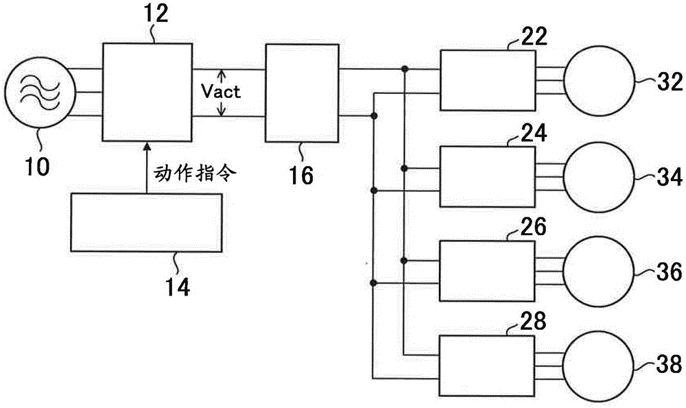
[0021] figure 1 It is a figure which shows the servomotor drive circuit of the injection molding machine of this embodiment. A power converter 12 is connected to the power supply unit 10. The power converter 12 is a device that converts the three-phase AC current and voltage supplied from the power supply unit 10 into a DC voltage. In addition, reference numeral 14 denotes a power converter control unit that issues operation commands to the power converter 12. The power storage unit 16 is connected to the power converter 12. In addition, in figure 1 Where Vact is the voltage of the power storage unit.

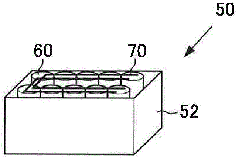
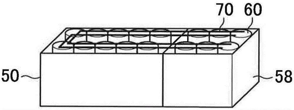
[0022] The voltage between the two lines connecting the power converter 12 and the power storage unit 16 is taken as the voltage of the power storage unit 16. In the present embodiment, the power storage unit 16 is composed of one or more power storage devices that are assembled and connected to the driving devices 22, 24, 26, 28 that drive various motors. Each drive device is...


PUM


Abstract

Disclosed is a control method for an injection molding machine, which is provided with a movable part, an electric storage device configured to store energy, and an energy supply unit configured to supply at least some of necessary energy for operation of the movable part from the electric storage device. In this injection molding machine control method, an amount of energy storable in the electric storage device is changed based on an energy index value as an index of the necessary energy for the operation of the movable part.

Description

Technical field [0001] The invention relates to a control method of an injection molding machine. Background technique [0002] In an injection device or a mold clamping device of an injection molding machine, a servo motor is generally used to drive a movable part such as a screw or a movable plate, and driving power is supplied from the motor driving device to the servo motor to drive the movable part forward and backward. Here, in the injection device, when the screw is moved forward and backward at a high speed during injection, even if a mold clamping force is generated in the mold clamping device in the same manner, large electric power is required. [0003] In the case of driving such a servo motor with high output, it is necessary to supply large electric power from the pump to the servo motor. However, since a large power supply capacity is required to supply all these large powers from the power from the main power supply, the cost of the main body of the molding machine...

Claims


Application Information

Patent Timeline
Patent Type & Authority Applications(China)
IPC IPC(8): B29C45/76
CPCB29C45/76B29C2945/76026B29C2945/76518B29C45/7666B29L2031/772
Inventor 内山辰宏小山秀树漆崎哲阳
Owner FANUC LTD
Why Eureka
Try Eureka