Connecting structure for tire pressure monitoring sensor and inflating valve

A technology of tire pressure monitoring and connection structure, which is applied in tire measurement, tire inflation valve, tire parts, etc. It can solve the problems of falling off, poor connection reliability, loosening of electronic signal box and valve, and achieves convenient operation and simple structure , The effect of stabilizing the connection reliability

Inactive Publication Date: 2015-12-16
BAOLONG ANHUI AUTO PARTS
View PDF8 Cites 7 Cited by
  • Summary
  • Abstract
  • Description
  • Claims
  • Application Information

AI Technical Summary

Problems solved by technology

The tire pressure sensor TPMS generally includes an electronic signal box and monitoring electronic components inside the electronic signal box. Due to the closed structure of the tire, it is necessary to firmly and reliably connect the electronic signal box to the valve during installation, so as to Withstand the centrifugal force generated when the tire is rolling, so the installation of the tire pressure sensor is very difficult
The conventional installation method in the prior art is to process the internal thread on the valve. After the valve passes through the electronic signal box, the screw is used to engage the internal thread on the valve to realize the connection. In the actual application process, when the screw is not fully installed in place When it is used, it is easy to cause the electronic signal box and the valve to loosen or even fall off, and the connection reliability is poor

Method used


Image

  • Connecting structure for tire pressure monitoring sensor and inflating valve
  • Connecting structure for tire pressure monitoring sensor and inflating valve
  • Connecting structure for tire pressure monitoring sensor and inflating valve

Examples


Embodiment Construction

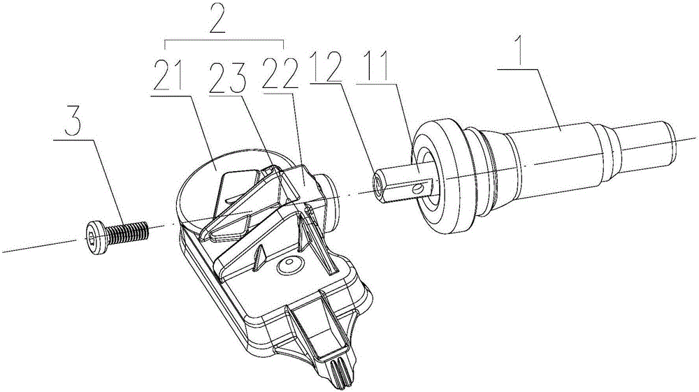
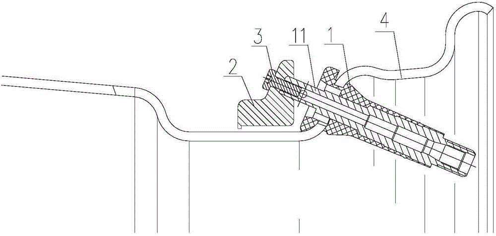
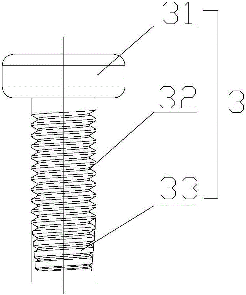
[0018] like Figures 1 to 3 shown, figure 1 It is a schematic structural diagram of the connection structure of a tire pressure monitoring sensor and a valve proposed by the present invention, figure 2 for figure 1 The schematic diagram of the connection structure of the middle tire pressure monitoring sensor and the valve mounted on the rim, image 3 for figure 1 Schematic diagram of the structure of the self-tapping screw.

[0019] refer to figure 1 , a connection structure between a tire pressure monitoring sensor and a valve proposed by an embodiment of the present invention includes: a valve 1, a tire pressure monitoring sensor 2 and a self-tapping screw 3, wherein:

[0020] A mounting hole 12 is coaxially provided on the nozzle rod 11 of the valve 1, and the mounting hole 12 has a smooth inner wall; a mounting table 22 is provided on the electronic signal box 21 of the tire pressure monitoring sensor 2, and a through hole 12 is provided on the mounting table 22. h...


PUM


Abstract

The invention discloses a connecting structure for a tire pressure monitoring sensor and an inflating valve. A mounting hole is formed in a valve rod of the inflating valve and provided with a smooth inner wall. A mounting table is arranged on an electronic signal box of the tire pressure monitoring sensor and provided with a through hole. The valve rod stretches into the middle of the through hole from the first side of the mounting table and abuts against the mounting table. A self-tapping screw penetrates the through hole from the second side of the mounting table and carries out tapping on the mounting hole of the valve rod. The self-tapping screw is directly engaged with an internal thread tapped in the mounting hole, and the end face of the self-tapping screw abuts against the mounting table, so that the inflating valve and the tire pressure monitoring sensor are in fastening connection. According to the connecting structure, the mounting hole is formed in the valve rod of the inflating valve and provided with the smooth inner wall, the self-tapping screw is directly engaged with the internal thread tapped in the mounting hole in the tapping process of the self-tapping screw, reliable locking threaded connection is formed, and an anti-loose effect is provided; and the connecting structure is simple and convenient to operate and has the stable connecting reliability.

Description

technical field [0001] The invention relates to a connection structure of a tire pressure monitoring sensor TPMS (TirePressureMonitoringSensor) and a valve. Background technique [0002] Since the size of the tire pressure will directly affect the safety of the car, it is necessary to set an electronic safety sensing device such as a tire pressure monitoring sensor on the tire valve to monitor the tire pressure in real time. The tire pressure sensor TPMS generally includes an electronic signal box and monitoring electronic components arranged inside the electronic signal box. Due to the closed structure of the tire, the electronic signal box needs to be firmly and reliably connected to the valve during the installation process. The tire pressure sensor is very difficult to install due to the centrifugal force generated by the tire as it rolls. The conventional installation method in the prior art is to process the internal thread on the valve, after the valve passes through...

Claims


Application Information

Patent Timeline
Patent Type & Authority Applications(China)
IPC IPC(8): B60C23/04B60C29/02
CPCB60C23/0494
Inventor 王贤勇陈志东李强杨庭华洪东登
Owner BAOLONG ANHUI AUTO PARTS
Why Eureka
Try Eureka