
A glue spraying structure for a rock wool centrifuge

A centrifuge and glue spraying technology, which is applied in glass manufacturing equipment, manufacturing tools, etc., can solve the problems affecting rock wool production quality, increasing production cost, affecting fiber quality, etc., and achieves simple structure, support and vibration prevention, and glue spraying uniform effect

Inactive Publication Date: 2017-07-28
GUANGDE SKD ROCKWOOL MFG
View PDF5 Cites 1 Cited by
  • Summary
  • Abstract
  • Description
  • Claims
  • Application Information

AI Technical Summary

Problems solved by technology

[0002] In the process of rock wool production, the melt of rock wool melted by the cupola is combined with the rock wool adhesive to form fibers under the action of four centrifugal rollers in the centrifuge. The uniformity of glue spraying will affect the quality of the fiber, and then affect The production quality of rock wool is affected, and the production cost is also increased. At the same time, the centrifugal roller on the centrifuge rotates very fast in the working state, and it is difficult to avoid the vibration of the centrifugal shaft. Under the vibration generated by the high-speed rotation of the centrifugal shaft It will cause the glue spray pipe to be worn or cut off. At the same time, it may also cause the cooling water in the cavity of the centrifugal roller to leak into the glue spray pipe, so that the sprayed adhesive is mixed with cooling water, which affects the fiber quality. The glue spraying pipe is relatively long, and it is difficult to support it only by the support at the rear end of the centrifugal roller and the copper sleeve at the glue nozzle of the spraying pipe.

Method used


Image

  • A glue spraying structure for a rock wool centrifuge
  • A glue spraying structure for a rock wool centrifuge
  • A glue spraying structure for a rock wool centrifuge

Examples


Embodiment Construction

[0015] In order to enhance the understanding of the present invention, the present invention will be described in further detail below in conjunction with the accompanying drawings and embodiments, which are only used to explain the present invention and do not limit the protection scope of the present invention.

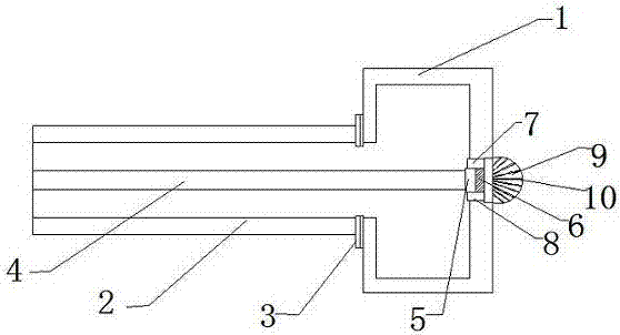
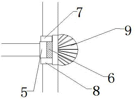
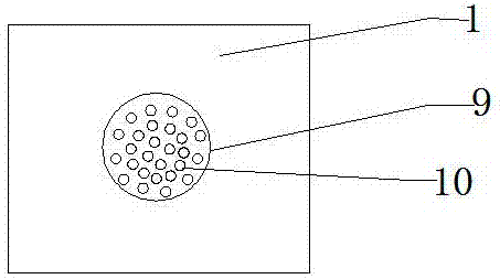
[0016] Such as Figure 1-3 As shown, a glue spraying structure of a rock wool centrifuge of the present invention includes a centrifugal roller 1 and a centrifugal shaft 2, the centrifugal roller 1 and the centrifugal shaft 2 are connected by a flange 3, and a glue spraying pipe 4 is arranged at the center of the centrifugal shaft 2, and The position where the glue spraying pipe 4 is in contact with the centrifugal roller 1 is provided with a shockproof shockproof gasket 5, and the end of the glue spraying pipe 4 is provided with a sealing ring 6, and the position where the shockproof washer 5 and the sealing ring 6 are in contact is provided. The first fixing block...


PUM


Abstract

The invention provides a glue spraying structure for a rock wool centrifuge, which includes a centrifugal roller and a centrifugal shaft. The centrifugal roller and the centrifugal shaft are connected by a flange. There is an anti-vibration washer at the position, and a sealing ring is provided at the end of the spray pipe, and a first fixed block and a second fixed block for fixing the anti-vibration washer and the sealing ring are arranged at the position where the anti-vibration washer and the sealing ring are in contact, and the spray pipe The glue spraying port is connected with the hemispherical glue spraying head set in the center of the outer side of the centrifugal roller. The inner and outer layers of the anti-shock gasket are made of wear-resistant silica gel, and the middle is made of rubber. A small tube, several small tubes are connected to the nozzles arranged on the hemispherical glue spray head, and the glue spray pipe, small tube, and hemispherical glue spray head are all stainless steel. The invention has simple structure and reasonable design, not only can effectively support and prevent the vibration of the glue spraying pipe, but also can make the glue spray evenly and improve the fiber quality.

Description

technical field [0001] The invention relates to the field of rock wool production equipment, in particular to a glue spraying structure of a rock wool centrifuge. Background technique [0002] In the process of rock wool production, the melt of rock wool melted by the cupola is combined with the rock wool adhesive to form fibers under the action of four centrifugal rollers in the centrifuge. The uniformity of glue spraying will affect the quality of the fiber, and then affect The production quality of rock wool is affected, and the production cost is also increased. At the same time, the centrifugal roller on the centrifuge rotates very fast in the working state, and it is difficult to avoid the vibration of the centrifugal shaft. Under the vibration generated by the high-speed rotation of the centrifugal shaft It will cause the glue spray pipe to be worn or cut off. At the same time, it may also cause the cooling water in the cavity of the centrifugal roller to leak into th...

Claims


Application Information

Patent Timeline
Patent Type & Authority Patents(China)
IPC IPC(8): C03B37/00
Inventor 汪传峰
Owner GUANGDE SKD ROCKWOOL MFG
Learn More