Hidden beam floor constructional column structure and construction method thereof

A construction method and technology for constructing columns, which are applied in building construction, construction, and building material processing, etc., can solve problems such as inability to reach corners of binding steel cages, floor slabs drilled through and rotten, and hidden quality problems, so as to eliminate hidden quality problems. , Reduce costs and facilitate the effect of pouring construction

Active Publication Date: 2015-12-16
CHENGDU NO 4 CONSTR ENG
View PDF7 Cites 6 Cited by
  • Summary
  • Abstract
  • Description
  • Claims
  • Application Information

AI Technical Summary

Problems solved by technology
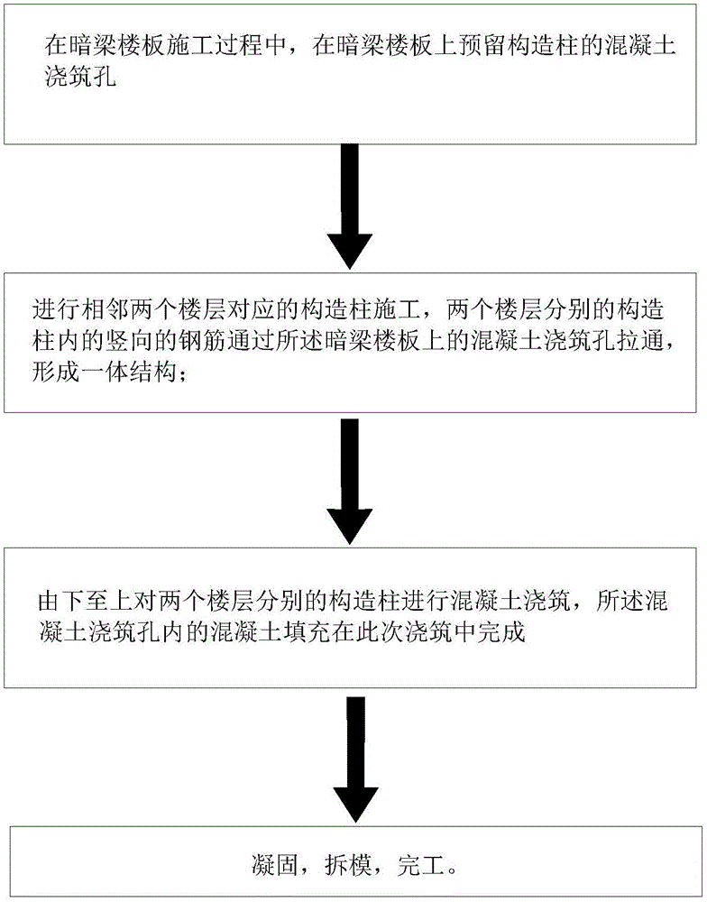
[0003] The upper and lower ends of the structural column are connected to the floor. In general, the floor is equipped with beams, and the beams are set under the floor. The general structural column is directly planted with reinforcement, and the two ends of the reinforcement are connected to the next floor. The top surface of the floor slab and the beams below the floor slab of the previous floor. At this time, the construction column formwork leaves an opening on the side of the top for pouring concrete. Fill it with concrete, and, for the case of setting structural columns between the hidden beam floors, since the beams of the hidden beam floors are set inside the floors and do not extend beyond the lower surface of the floors, when setting the structural columns for planting reinforcement, the column support The mold leaves an opening on the side of the top for pouring concrete, but after the mold is finally closed, there will be a larger gap or a circle, or the concrete cannot be filled to the top floor. At this time, the prior art is also hand-applied concrete In this case, the construction quality of the structural column will be very poor, and its effect of resisting shear force will also be affected. At the same time, there are many disadvantages in this way of planting reinforcement, as follows :
[0004] ①The drilling of the planting bars is too close, and the tying reinforcement cage cannot reach the corner, and there is a quality risk in the steel bars of the tying structural column; The steel bars of the structural columns are shifted; ③The upper and lower floors are planted in the same narrow area at the same time, and the positions of the upper and lower planted bars cannot be staggered. There is an overlapping length between the upper and lower bars of the bound steel cage, which will lead to a large waste of steel bars and increase costs; The open type is not conducive to the compactness of concrete pouring on the upper part of the structural column, resulting in a loose connection between the structural column and the main structure, and the upper part is prone to gaps, leaving quality problems
⑥ Rebar planting requires additional payment for rebar planting, which increases the cost of the project department

Method used


Image

  • Hidden beam floor constructional column structure and construction method thereof
  • Hidden beam floor constructional column structure and construction method thereof

Examples


Embodiment 1

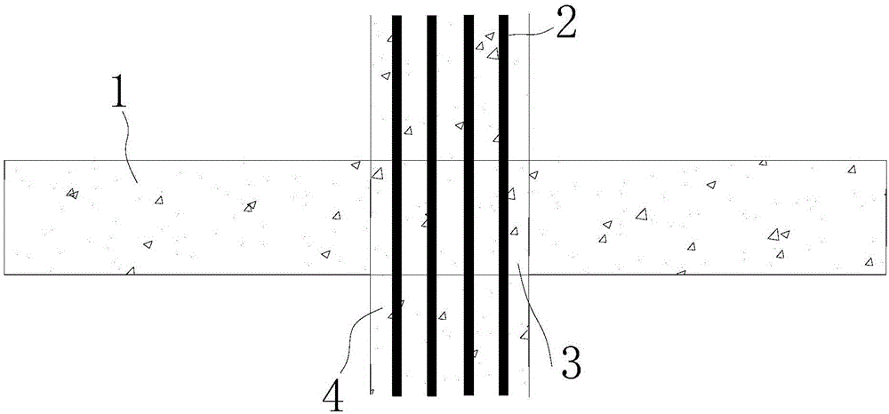
[0039] Such as figure 1 , a concealed beam floor construction column structure, which comprises:

[0040] Concealed beam floor 1 (there are walls on the floor that need beams to bear the load, or tie beams need to be installed between columns, but the beams cannot protrude from the bottom of the slab to affect the space use requirements. In this case, set reinforcement bars 2 on the slab play the role of the beam, that is, the hidden beam);

[0041] A reinforcing cage, in which a plurality of reinforcing bars 2 are vertically arranged, and the upper and lower ends of the reinforcing bars 2 are connected to the concealed beam floor 1;

[0042]A columnar structure 4, the columnar structure 4 is formed by pouring concrete, the steel bar 2 is penetrated inside the columnar structure 4, and the upper and lower ends of the columnar structure 4 are connected to the concealed beam floor 1;

[0043] The structural column runs through two adjacent floors, the steel bars 2 in the resp...

Embodiment 2

[0051] A floor construction column structure, comprising:

[0052] A reinforcing cage, in which a plurality of reinforcing bars 2 are arranged vertically, and the upper and lower ends of the reinforcing bars 2 are connected to the floor 1;

[0053] A columnar structure 4, the columnar structure 4 is formed by pouring concrete, the steel bar 2 is pierced inside the columnar structure 4, and the upper and lower ends of the columnar structure 4 are connected to the floor;

[0054] The structural column runs through two adjacent floors, the steel bars 2 in the structural columns of the two floors are connected as a whole, and the columnar structure 4 is arranged around the steel bar 2 at the intersection of the two floors.


PUM


Abstract

The invention relates to the field of constructional column construction, in particular to a hidden beam floor constructional column structure and a construction method thereof. The constructional column structure comprises a steel reinforcement cage and a column-shaped structure, wherein a plurality of rebars are vertically arranged in the steel reinforcement cage, and the upper end lower ends of the rebars are connected with hidden beam floors; the column-shaped structure is formed by pouring of concrete; the rebars are arranged in the column-shaped structure in a penetration manner, and the upper and lower ends of the column-shaped structure are connected with the floors; the constructional column penetrates through two adjacent storeys, and rebars in separate constructional columns of the two storeys are integrally connected; and the column-shaped structure are arranged around the rebars at a junction part of the two storeys. The application of the invention aims to provide the floor constructional column structure which has the advantages that rebars are saved; the constructional column structure can be firmly connected with a main body; rebar displacement is avoided; pouring difficulty is reduced; and the cost is lowered. Meanwhile, the relevant construction method is also provided.

Description

technical field [0001] The invention relates to the construction field of structural columns, in particular to the structural column structure and construction method of a concealed beam floor slab. Background technique [0002] In the specified part of the wall of the masonry house, the concrete column is made according to the structural reinforcement and the construction sequence of laying the wall first and then pouring the concrete column. It is usually called a concrete structural column, referred to as a structural column. The seismic performance of the body structure is mainly not to bear the vertical load, but to resist the force of shear force, earthquake and other lateral loads; [0003] The upper and lower ends of the structural column are connected to the floor. In general, the floor is equipped with beams, and the beams are set under the floor. The general structural column is directly planted with reinforcement, and the two ends of the reinforcement are connect...

Claims


Application Information

Patent Timeline
Patent Type & Authority Applications(China)
IPC IPC(8): E04B1/20E04G21/00
Inventor 谢惠庆欧定文刘永红李熊飞杜斌刘庆土李阳权向前峰吴宇宏王红委罗佳罗颖
Owner CHENGDU NO 4 CONSTR ENG
Why Eureka
Try Eureka