A concentric double-pipe sand flushing device
A concentric double-pipe, sand flushing technology, used in flushing wellbore, wellbore/well components, earth-moving drilling, etc. The effect of strong sprinting force and fast flow rate
- Summary
- Abstract
- Description
- Claims
- Application Information
AI Technical Summary
Problems solved by technology
Method used
Image
Examples
Embodiment 1
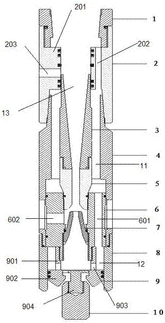
[0022] like figure 1 As shown, a concentric double-pipe sand flushing device includes an upper joint 1, a backwash bridge joint 2, a diffuser pipe 3, a work cylinder 4, a throat pipe 5, a jet bridge joint 6, a nozzle 7, a lower joint 8, a support Seat 9, support valve 10;
[0023] The backwash bridging head 2 is a tubular joint with large upper and lower apertures and a convex body 201 in the middle. The convex body 201 is provided with a longitudinal channel I202 parallel to the central hole of the backwash bridging head 2;
[0024] The jet bridging head 6 is provided with a longitudinal channel II601 parallel to the center hole of the jet bridging head 6;
[0025] The support seat 9 is a T-shaped cylinder support composed of a small-aperture cylinder 901 and a large-aperture cylinder 902, and the centerlines of the small-aperture cylinder 901 and the large-aperture cylinder 902 are located on the same straight line;
[0026] The lower end of the upper joint 1 is connected ...
Embodiment 2
[0034] On the basis of Example 1, in order to return to the concentric double pipes on the ground for the flowback liquid to diffuse in the process of flowback, the central hole of the diffusion pipe 3 is that the aperture of the upper end is larger than the lower end, and the diffusion pipe 3 is connected with the convex The convex surface of the body 201 is in sealing contact with the sealing ring, and the diffusion pipe 3 and the throat pipe 5 are fixedly connected by threads, and a sealing ring is provided between the diffusion pipe 3 and the throat pipe 5 . The diameter of the lower end of the diffuser tube 3 is relatively small. Under the strong pressure of the flowback liquid, a large amount of pressure will accumulate at the small diameter end, and when it passes through the small aperture section, a rapid eruption will be formed, and it can quickly rush out of the central channel 13 back to the ground.
Embodiment 3
[0036]On the basis of Embodiment 1, a T-shaped block 904 perpendicular to the lower end surface is fixed in the middle of the lower end surface of the large-diameter cylinder 902 of the support seat 9, and the support valve 10 is slidably connected to the T-shaped block. 904, the discharge volume of the support seat 9 is controlled by sliding up and down on the T-shaped block. The support valve 10 and the support seat 9 are connected by sliding. Under the action, away from the support seat 9, the channel formed by the support seat 9 and the support valve 10 is opened, and the well flushing fluid is quickly discharged from the support seat 9, activating the sand settling or other mechanical particles at the bottom of the well. It has a high flow rate and strong sprinting force. The sand mixing fluid cannot return from the oil casing annulus due to the blocking of the cup packer. When the sand flushing device touches the bottom of the well, the support valve 10 is relatively 9 g...
PUM
 Abstract
Description
Claims
Application Information
 - R&D
- Intellectual Property
- Life Sciences
- Materials
- Tech Scout
- Unparalleled Data Quality
- Higher Quality Content
- 60% Fewer Hallucinations
Browse by: Latest US Patents, China's latest patents, Technical Efficacy Thesaurus, Application Domain, Technology Topic, Popular Technical Reports.
© 2025 PatSnap. All rights reserved.Legal|Privacy policy|Modern Slavery Act Transparency Statement|Sitemap|About US| Contact US: help@patsnap.com

