Dry gas seal device

A dry gas sealing and sealing support technology, applied in the direction of engine sealing, engine components, mechanical equipment, etc., can solve the problems of high rigidity of the gas film, deformation, easy collision between the compensation ring and the active ring, etc. High membrane stiffness, low leakage, enhanced effect of hydrodynamic pressure

Inactive Publication Date: 2015-12-16
LANZHOU UNIVERSITY OF TECHNOLOGY
View PDF7 Cites 13 Cited by
  • Summary
  • Abstract
  • Description
  • Claims
  • Application Information

AI Technical Summary

Problems solved by technology

[0005] In order to solve the problems that the auxiliary sealing O-ring of the compensation ring is easily deformed due to high temperature and the compensation ring and the active ring are prone to rubbing when the dry gas seal is applied to high-temperature and large-amplitude vibration equipmen

Method used


Image

  • Dry gas seal device
  • Dry gas seal device
  • Dry gas seal device

Examples


Embodiment Construction

[0024] The technical scheme of the present invention will be introduced below in conjunction with the accompanying drawings.

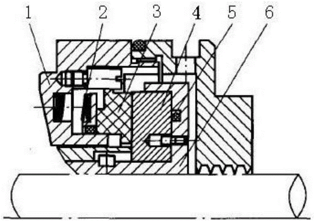
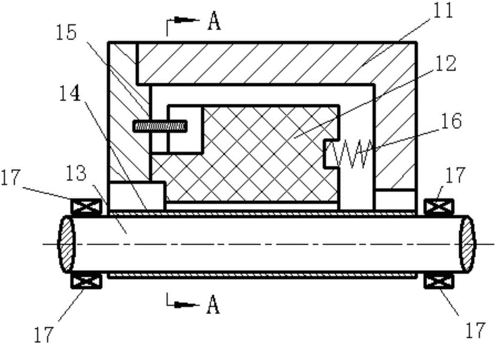
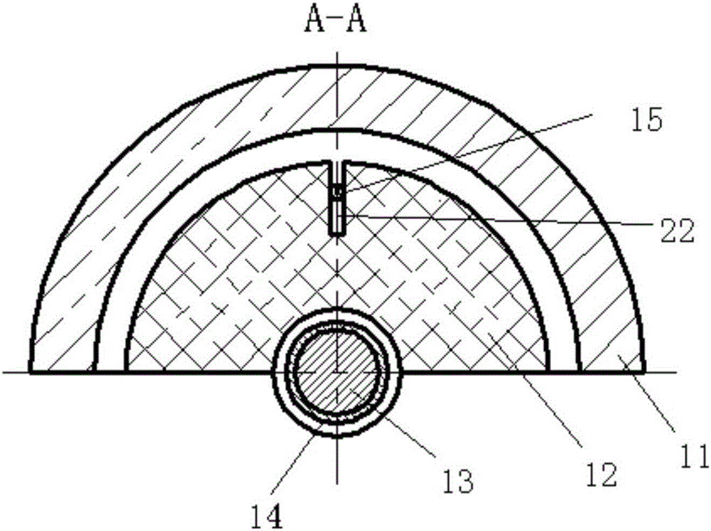
[0025] like figure 2 and image 3 As shown, the dry gas sealing device of the present invention includes a sealing support 11 , a compression spring 16 , a floating ring 12 , a rotating shaft 13 , a shaft sleeve 14 , and a positioning pin 15 . The sealing support 11 is an annular structure, the middle part of the sealing support 11 is provided with a bearing 17, and the rotating shaft 13 is assembled on the bearing 17, so that the rotating shaft 13 is fixedly connected with the sealing support 11. The axle sleeve 14 is interference fit on the rotating shaft 13, and the axle sleeve 14 rotates with the rotating shaft 13, as Figure 4 As shown, the outer wall of the shaft sleeve 14 is provided with a helical groove 18, a platform 19 and a dam 20, wherein the platform 19 refers to the surface between the two helical grooves 18, and the dam 20 refers to ...


PUM

PropertyMeasurementUnit
Depthaaaaaaaaaa
Helix angleaaaaaaaaaa
Depthaaaaaaaaaa

Abstract

The invention belongs to the technical field of mechanical seals, and provides a dry gas seal device to solve the problems that when a current dry gas seal is applied to high-temperature large-amplitude vibration equipment, an auxiliary seal O-type ring of a compensation ring is likely to deform due to high temperature, and the compensation ring and an active ring are likely to rub. The dry gas seal device comprises a seal support, a pressure spring, a floating ring, a rotary shaft, a shaft sleeve and a locating pin. Bearings are arranged in the middle of the seal support, and the rotary shaft is assembled on the bearings. Spiral grooves, tables and dams are arranged on the outer wall of the shaft sleeve, and the shaft sleeve is arranged on the rotary shaft. The floating ring is located in the seal support and arranged on the shaft sleeve in a sleeving manner. One end of the floating ring and the seal support are circumferentially fixed through the locating pin, and the other end of the floating ring is connected with the pressure spring. The dry gas seal device is good in opening characteristic, high in gas film rigidity, stable in running and capable of adapting to shaft end seals of the high-temperature large-amplitude vibration equipment.

Description

technical field [0001] The invention belongs to the technical field of mechanical seals, and in particular relates to a dry gas sealing device. Background technique [0002] Flue gas turbines and gas turbines in petrochemical equipment are high-temperature, large-amplitude vibration equipment. The working environment temperature is high and the vibration amplitude during work is large. Whether the device can operate normally has attracted the attention of enterprises. At present, comb labyrinth seals are still used in high-temperature, large-amplitude vibration equipment, but because the comb-tooth labyrinth seals often cause large leakage due to excessive gaps between the comb teeth and the shaft, the seal fails. Therefore, it is necessary to find a seal with good sealing performance and Sealing device with stable system performance. [0003] As a non-contact mechanical seal, dry gas seal has been widely used in the shaft end seal of high-speed rotating equipment. like ...

Claims


Application Information

Patent Timeline
IPC IPC(8): F16J15/40
Inventor 丁雪兴张伟政俞树荣冯建国陆俊杰翟霄陈金林
Owner LANZHOU UNIVERSITY OF TECHNOLOGY
Why Eureka
Try Eureka