Tandem arc groove type bidirectional rotary sealing end face structure
A two-way rotating, sealed-end technology, applied in the direction of engine seals, engine components, mechanical equipment, etc., can solve the problems of seal component damage, seal failure, etc., to achieve good diversion effect, low seal friction power consumption, strong fluid dynamic pressure and the effect of static pressure
- Summary
- Abstract
- Description
- Claims
- Application Information
AI Technical Summary
Problems solved by technology
Method used
Image
Examples
Embodiment 1
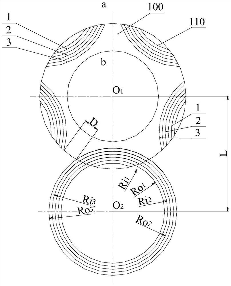
[0027] Embodiment 1 A tandem circular arc groove type bidirectional rotary seal end face structure according to the present invention includes a static ring and a moving ring for mechanical end face sealing, and both the static ring and the moving ring have a sealing end face 100, The outer ring edge of the sealing end face 100 is the sealing high pressure side (ie the upstream side) a, the inner ring edge of the sealing end face is the sealing low pressure side (ie the downstream side) b, and the sealing low pressure side of the sealing end face An annular sealing dam is provided, and five series of circular arc dynamic pressure groove groups 110 are uniformly distributed along the circumference of the sealing end surface on the sealing end face 100 of the static ring and / or moving ring, and each group of serial arc dynamic pressure groove groups The group includes 3 concentric arc grooves, which are respectively named as the first arc groove 1, the second arc groove 2 and the...
Embodiment 2
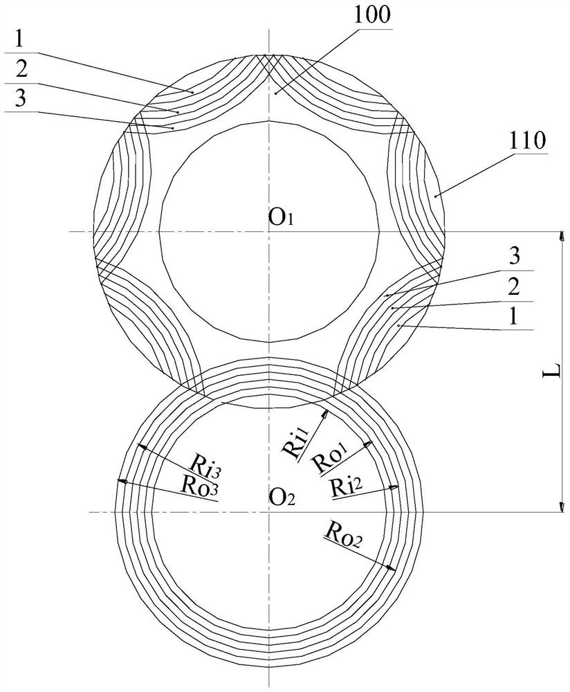
[0031] Embodiment 2 is attached figure 2 As shown, the difference between the tandem circular arc groove type bidirectional rotary seal end face structure described in this embodiment and embodiment 1 is that the seal end face 100 is evenly distributed along the circumferential direction with 7 tandem arc dynamic pressure groove groups 110. The series of circular arc groove groups partially overlap with adjacent circular arc groove groups; other structures are the same.
[0032] Specifically, taking a single concentric arc groove as an example, the first arc groove 1, the second arc groove 2 and the third arc groove 3 are all represented by O 2 is the center of the circle, and the inner diameter of the first arc groove is Ri 1 mm, the outer diameter is Ro 1 mm; the inner diameter of the second arc groove is Ri 2 mm, the outer diameter is Ro 2 mm; the inner diameter of the third arc groove is Ri 3 mm, the outer diameter is Ro 3 mm. The center O of the sealing end ...
Embodiment 3
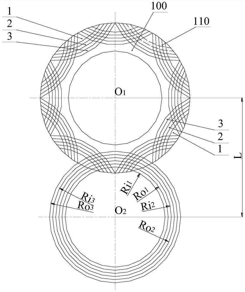
[0033] Embodiment 3 is attached image 3 As shown, the difference between the tandem arc groove type bidirectional rotary seal end face structure described in this embodiment and the embodiment 1 is that: the seal end face 100 is evenly distributed along the circumferential direction with 8 tandem arc dynamic pressure groove groups 110, the tandem arc groove group 110 is partially overlapped with the adjacent arc groove group; other structures are the same.
[0034] Specifically, as attached image 3 As shown, taking a single concentric arc groove as an example, the first arc groove 1, the second arc groove 2 and the third arc groove 3 are all represented by O 2 is the center of the circle, and the inner diameter of the first arc groove is Ri 1 mm, the outer diameter is Ro 1 mm; the inner diameter of the second arc groove is Ri 2 mm, the outer diameter is Ro 2 mm; the inner diameter of the third arc groove is Ri 3 mm, the outer diameter is Ro 3 mm. The center O o...
PUM
 Abstract
Description
Claims
Application Information
 - R&D
- Intellectual Property
- Life Sciences
- Materials
- Tech Scout
- Unparalleled Data Quality
- Higher Quality Content
- 60% Fewer Hallucinations
Browse by: Latest US Patents, China's latest patents, Technical Efficacy Thesaurus, Application Domain, Technology Topic, Popular Technical Reports.
© 2025 PatSnap. All rights reserved.Legal|Privacy policy|Modern Slavery Act Transparency Statement|Sitemap|About US| Contact US: help@patsnap.com


