Mechanical seal end face structure of variable-depth spiral T-shaped groove

A mechanical seal and spiral groove technology, which is applied in the direction of engine seals, mechanical equipment, engine components, etc., can solve the problems of not being able to discharge wear and debris in time, short service life, and reduced performance of mechanical seals, and achieve good hydrodynamic pressure effects , Improve the effect of hydrodynamic pressure, improve the effect of temperature distribution

Active Publication Date: 2019-11-05
BEIHANG UNIV
View PDF8 Cites 2 Cited by
  • Summary
  • Abstract
  • Description
  • Claims
  • Application Information

AI Technical Summary

Problems solved by technology

[0004] Due to the above-mentioned problems in the use of microscopic cavity and pumping groove alone, in recent years, it has been proposed to use the combination of microscopic cavity and pumping groove, which not only improves the dynamic performance of the seal, but also reduces the leakage, but there are discharges in the work. The problem of insufficient crumb capacity
The wear and tear debris cannot be discharged in time, resulting in increased frictional heat generation between the sealing end faces and uneven temperature distribution, resulting in deformation of the end faces. In severe cases, cracks will occur on the sealing end faces, which greatly reduces the performance of the mechanical seal.
At the same time, the sealing performance is unstable, and it is easy to be affected by the fluctuation of liquid film pressure to generate vibration, resulting in poor lubrication effect when starting and stopping, end face wear and short service life.

Method used


Image

  • Mechanical seal end face structure of variable-depth spiral T-shaped groove
  • Mechanical seal end face structure of variable-depth spiral T-shaped groove
  • Mechanical seal end face structure of variable-depth spiral T-shaped groove

Examples


Embodiment Construction

[0023] The present invention will be further described below in conjunction with the accompanying drawings.

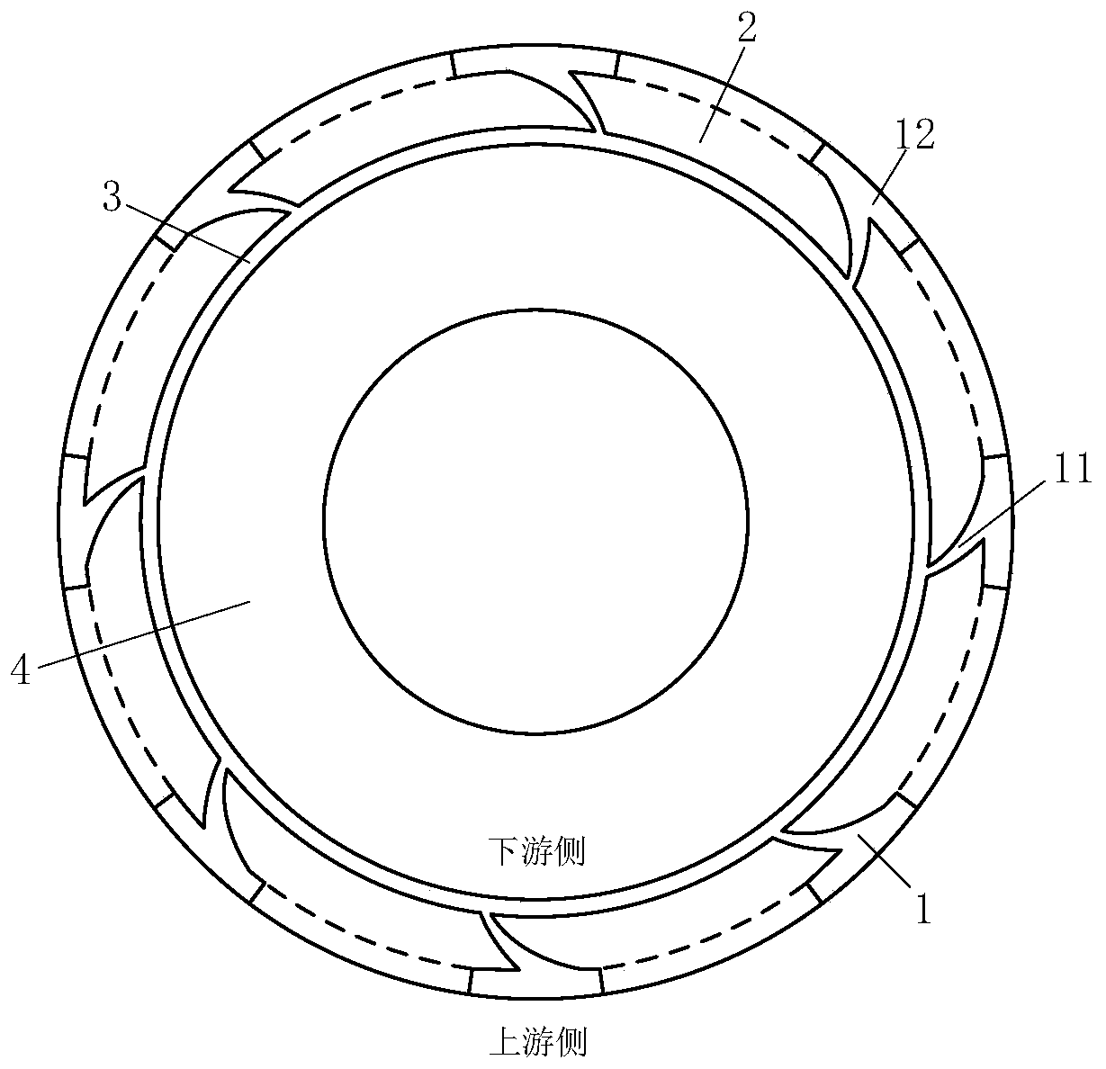
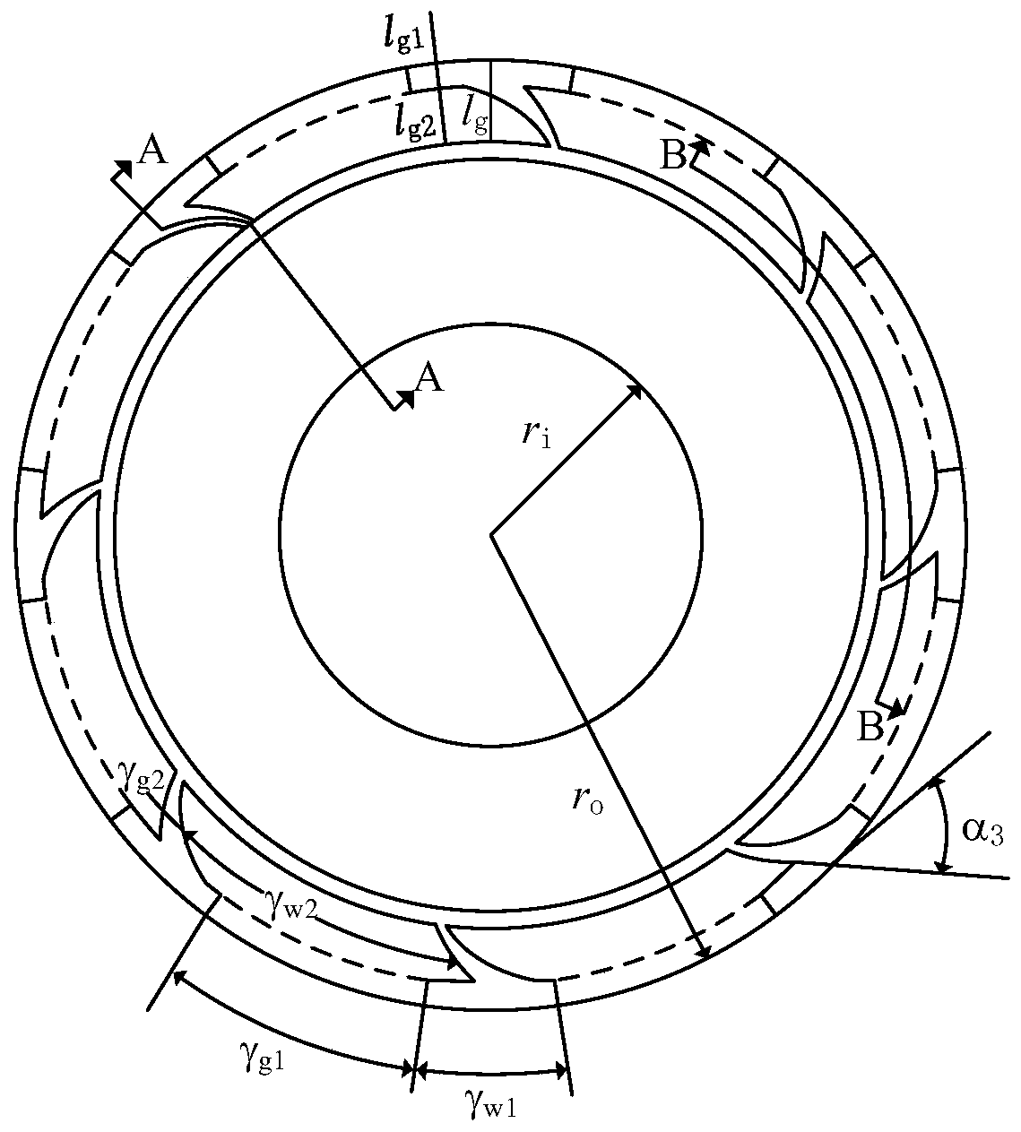
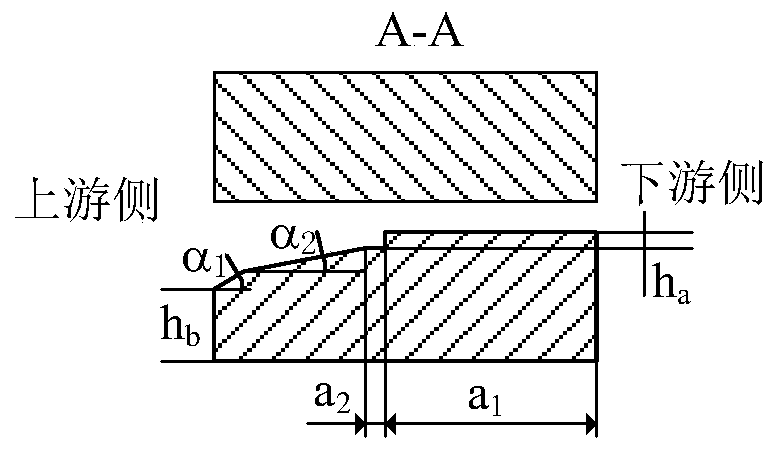
[0024] refer to Figure 1 ~ Figure 4 , a mechanical seal end face structure of a variable-depth spiral T-shaped groove, including a moving ring and a static ring of a mechanical seal, one side of the end face of the moving ring or the static ring is the high-pressure side, that is, the upstream, and the end face of the moving ring or the static ring The other side is the low-pressure side, that is, the downstream side. A series of variable-depth spiral T-shaped grooves 1 are arranged on the end surface of the moving ring. Sealing weirs 2 are arranged between the variable-depth spiral T-shaped grooves 1. The variable-depth spiral T-shaped grooves 1 It communicates with the circumferential ring groove 3, and a sealing dam 4 is arranged between the circumferential ring groove 3 and the downstream side.

[0025] The number of the variable-depth spiral T-shaped grooves is ...


PUM


Abstract

The invention discloses a mechanical seal end face structure of a variable-depth spiral T-shaped groove. The structure comprises a mechanical seal movable ring and a mechanical seal static ring, wherein one side of the end face of the movable ring or the static ring is provide with a high-pressure side, namely an upstream side, and the other side of the end face of the movable ring or the static ring is provide with a low-pressure side, namely a downstream side; variable-depth spiral T-shaped grooves are formed in the end face of the movable ring, seal weirs are arranged among the variable-depth spiral T-shaped grooves, the variable-depth spiral T-shaped grooves communicate with a circumferential annular groove, and a seal dam is arranged between the circumferential annular groove and thedownstream side; and the number of the variable-depth spiral T-shaped grooves is an even number in 8 - 24, and the radial width of the whole variable-depth spiral T-shaped grooves accounts for less than one third of the radial width of the whole seal end face. According to the mechanical seal end face structure of the variable-depth spiral T-shaped groove, the fluid dynamic pressure effect is effectively improved, the working efficiency of mechanical seal is improved, and the sealing performance of the mechanical seal in a static state is ensured; and solid particles and the like can be timely discharged out of the seal end face, so that the friction between end surfaces is reduced, the temperature distribution is improved, and the problems of deformation and even mechanical seal end surface cracking caused by uneven heating of a seal ring are avoided.

Description

technical field [0001] The invention provides a variable-depth T-groove mechanical seal end face structure, specifically, a certain number of variable-depth spiral T-shaped grooves are opened on the end face of a moving ring, and belongs to the technical field of rotary shaft seals in fluid seals. Background technique [0002] Mechanical seal is a shaft sealing device of turbine rotating machinery, which is widely used in equipment in the fields of aerospace, petrochemical, medicine, food and energy. In the actual use of mechanical end seals, it is required to adapt to extreme working conditions such as high pressure, high speed, and sudden changes in working conditions, which leads to easy contact between the end faces of the seals, resulting in severe friction and wear on the end faces of the seals and is prone to failure; to achieve non-contact sealing , the seal end face clearance increases, resulting in increased leakage. [0003] Theoretical calculations and experimen...

Claims


Application Information

Patent Timeline
Patent Type & Authority Applications(China)
IPC IPC(8): F16J15/34F16N1/00
CPCF16J15/3408
Inventor 王岩谭春森申同圣寇桂岳
Owner BEIHANG UNIV
Why Eureka
Try Eureka