High temperature damper valve shaft adiabatic transmission mechanism and assembly method thereof

A transmission mechanism and heat insulation technology, which is applied in the direction of valve devices, engine components, valve operation/release devices, etc., can solve problems such as actuator overheating, actuator damage, space structure restrictions, etc., to ensure accuracy and high efficiency , the effect of high structural strength

Active Publication Date: 2018-06-26
MEGAUNITY ENVIRONMENTAL SOLUTIONS CO LTD
View PDF6 Cites 0 Cited by
  • Summary
  • Abstract
  • Description
  • Claims
  • Application Information

AI Technical Summary

Problems solved by technology

The electric or pneumatic actuators that drive the blades to rotate generally have a temperature resistance below 70°C, and the high temperature resistant actuators do not exceed 150°C. Heat conduction is very easy to cause damage to the actuator, and the valve shaft directly driven by the actuator is required to have a higher temperature. strength, otherwise the opening and closing function of the air valve cannot be realized, and it may also affect the operation of the entire high-temperature gas treatment system
The current high-temperature air valve has the following problems: 1) Due to heat conduction, the actuator is overheated and easily damaged; 2) The adiabatic transmission mechanism added to the valve shaft has low strength and is not suitable for large-size, high-torque air valves; 3) Limited by the space structure , the usual air valve external plus cooling system is not applicable

Method used


Image

  • High temperature damper valve shaft adiabatic transmission mechanism and assembly method thereof
  • High temperature damper valve shaft adiabatic transmission mechanism and assembly method thereof
  • High temperature damper valve shaft adiabatic transmission mechanism and assembly method thereof

Examples


Embodiment Construction

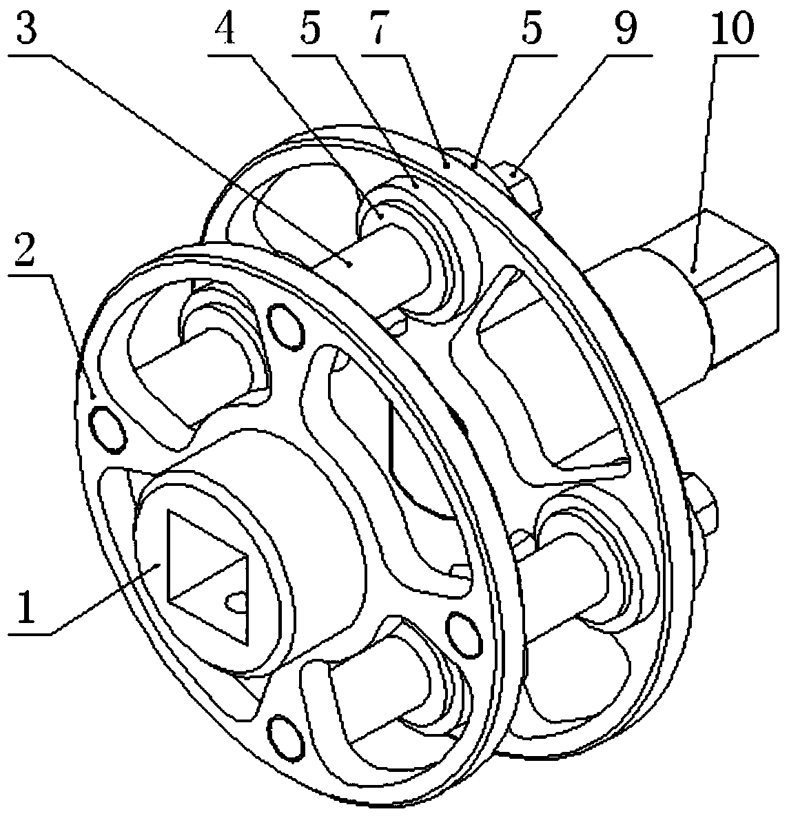
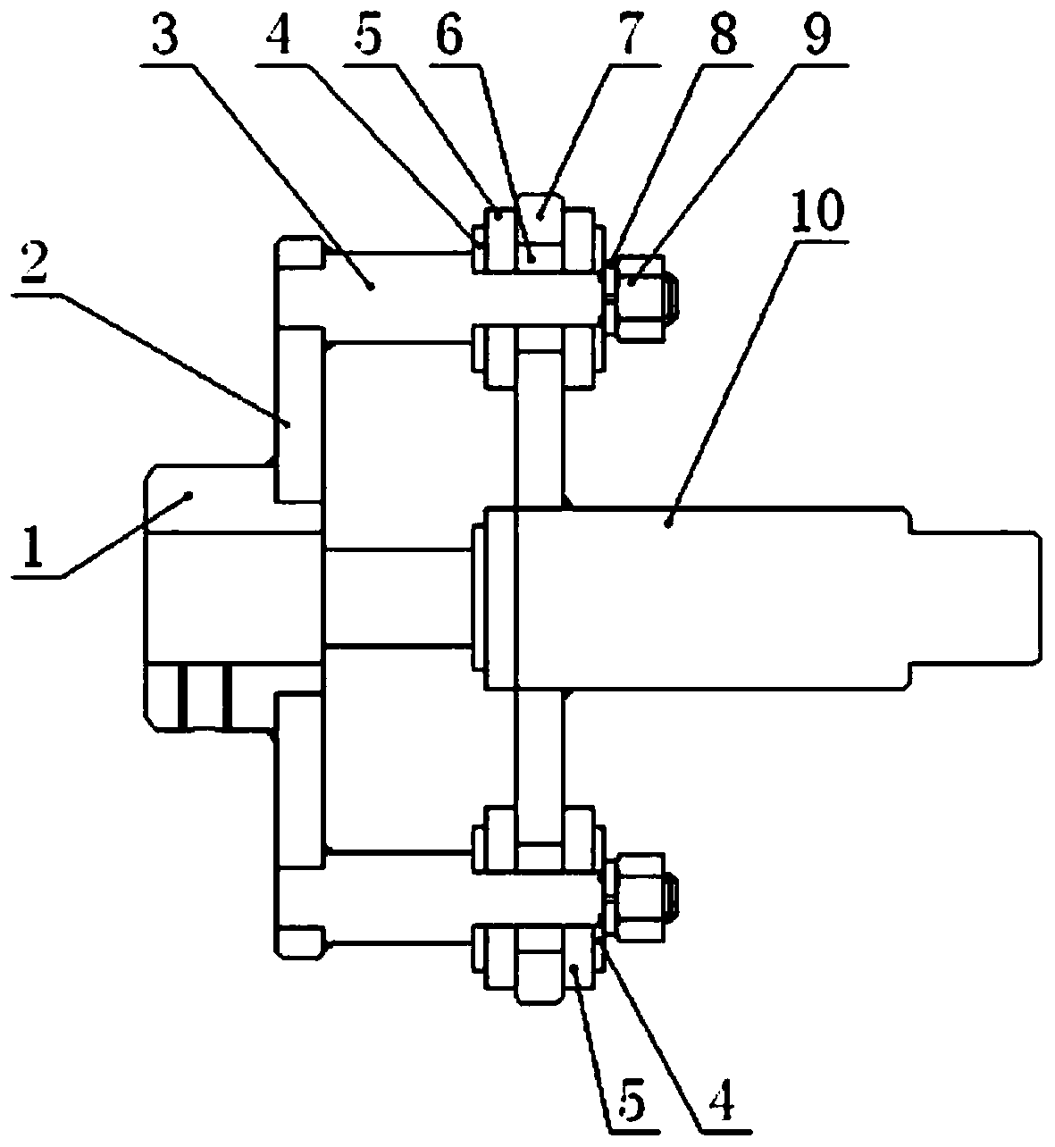
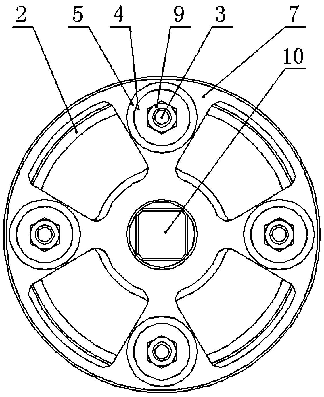
[0024] Attached below Figure 1-4 The present invention is described further:

[0025] The high-temperature damper valve shaft adiabatic transmission mechanism includes a main shaft connecting sleeve 1 connected with the damper valve shaft, the main shaft connecting sleeve 1 is fixedly connected to the main shaft turntable 2, and the main shaft turntable 2 is connected to the connecting shaft 3;

[0026] Both sides of the heat-insulating turntable 7 are fitted with heat-insulating mica pads 5, the gasket 4 is bonded to the heat-insulating mica pad 5, the heat-insulating turntable 7 is provided with a heat-insulating mica ring 6, and the connecting shaft 3 passes through the heat-insulating mica ring 6 in the heat-insulating turntable 7, and The heat-insulating mica pad 5 and the washer 4 attached to the outside of the heat-insulating turntable 7, the connecting shaft 3 is fastened and connected with the washer 4, the heat-insulation mica pad 5 and the heat-insulation turntable...


PUM


Abstract

The invention relates to a transmission device and an assembling method thereof, in particular to a heat insulation transmission device and an assembling method thereof, and discloses a high-temperature air valve shaft heat insulation transmission mechanism and an assembling method thereof. The high-temperature air valve shaft heat insulation transmission mechanism comprises a main shaft connecting sleeve connected with an air valve shaft. The main shaft connecting sleeve is fixedly connected with a main shaft rotary disc, and the main shaft rotary disc is connected with connecting shafts. Heat insulation mica gaskets are attached to the two sides of a heat insulation rotary disc. Washers are attached to the heat insulation mica gaskets. Heat insulation mica rings are arranged in the heat insulation rotary disc. The connecting shafts penetrate the heat insulation mica rings in the heat insulation rotary disc, the heat insulation mica gaskets and the washers, and the heat insulation mica gaskets and the washers are attached to the outer portion of the heat insulation rotary disc. The connecting shafts are in fastening connection with the washers, the heat insulation mica gaskets and the heat insulation rotary disc through hexagon nuts and spring washers. The high-temperature air valve shaft heat insulation transmission mechanism has the beneficial effects of being simple in structure, light, convenient to assemble, high in structural strength, good in heat insulation effect and very suitable for air valve structures with large torque and high temperature.

Description

technical field [0001] The invention relates to a transmission device and an assembly method thereof, in particular to an adiabatic transmission device and an assembly method thereof. Background technique [0002] In the ventilation pipeline system, the valve is the control element, and its main function is to isolate the equipment and the pipeline system, regulate the flow, prevent backflow, adjust and discharge the pressure, so the valve is a crucial device in the ventilation pipeline system. In the RTO exhaust gas treatment system, three ventilation valves are usually used. The two valves are linked to open and close in reverse. The two valves are driven by a large torque pneumatic or electric actuator. The temperature of the gas in the pipeline is above 500 °C. , The intermittent maximum temperature is sometimes 1200°C. The electric or pneumatic actuators that drive the blades to rotate generally have a temperature resistance below 70°C, and the high temperature resista...

Claims


Application Information

Patent Timeline
Patent Type & Authority Patents(China)
IPC IPC(8): F16K31/44F16L59/02
CPCF16K31/44F16L59/02F16L59/028
Inventor 赵勇赵新新苏向东才煜坤夏红梅姚伟强
Owner MEGAUNITY ENVIRONMENTAL SOLUTIONS CO LTD
Why Eureka
Try Eureka