Ball valve sealing testing apparatus
A testing device and sealing technology, which can be used in liquid/vacuum measurement for liquid tightness, and by measuring the acceleration and deceleration rate of fluid, etc., can solve the problems of uneven end face of ball valve, troublesome installation of ball valve, complicated operation process, etc. Achieve reasonable overall structure, improve sealing effect, and strengthen the effect of sealing effect
- Summary
- Abstract
- Description
- Claims
- Application Information
AI Technical Summary
Problems solved by technology
Method used
Image
Examples
Embodiment 1
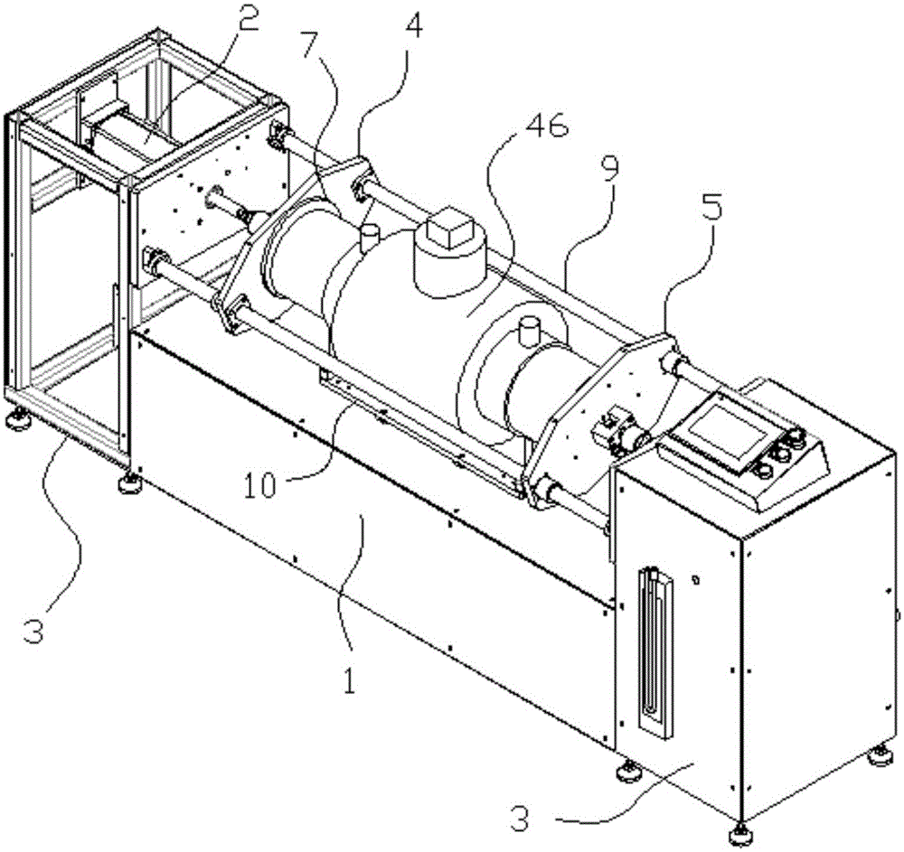
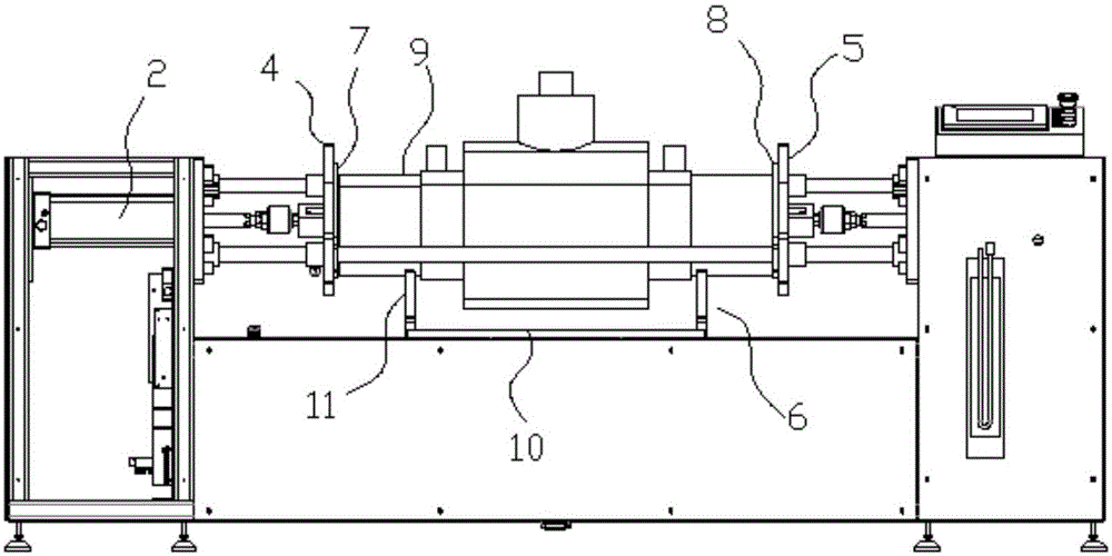
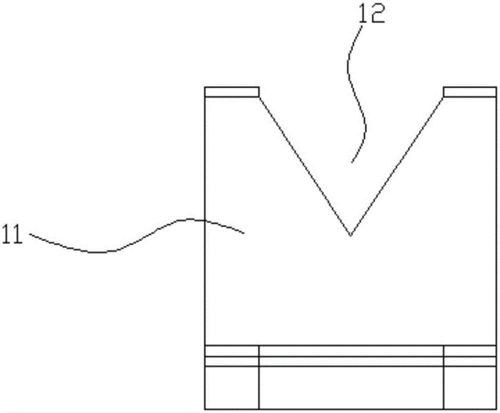
[0039] Embodiment 1: as Figure 1 to Figure 4 In the shown embodiment, a ball valve tightness testing device includes an air supply pump, an air pressure sensor 14, a main frame 1, two push plate cylinders 2, two side frames 3 with opposite inner surfaces, a main end cover 4, The auxiliary end cover 5, the main end cover and the auxiliary end cover are parallel to each other, the main frame is provided with a ball valve support frame 6 for supporting the ball valve to be tested, and the two push plate cylinders are respectively arranged on the two side frames The piston rod of one of the push pedal cylinders is connected to the main end cover, and the piston rod of the other push pedal cylinder is connected to the auxiliary end cover. The surface of the main end cover near the ball valve support frame is provided with a Measure the main elastic sealing ring pad 7 at the pipe end of the ball valve. The surface of the auxiliary end cover close to the ball valve support frame sid...
Embodiment 2
[0041] Embodiment 2: as Figure 5 to Figure 7 In the shown embodiment, a ball valve tightness testing device includes an air supply pump 13, an air pressure sensor, a main frame, two push plate cylinders, two side frames with opposite inner surfaces, a main end cover, and a secondary end cover, The main end cover and the auxiliary end cover are parallel to each other. The main frame is provided with a ball valve support frame for supporting the ball valve to be tested. Two push plate cylinders are respectively arranged on the two side frames, and one of the push plate The piston rod of the cylinder is connected to the main end cover, and the piston rod of the other push plate cylinder is connected to the auxiliary end cover. The surface of the main end cover close to the ball valve support frame is provided with a main spring for contacting the pipe end of the tested ball valve. A sealing ring pad 7, the surface of the auxiliary end cover close to the ball valve support frame ...
Embodiment 3
[0049] Embodiment 3: the basic structure and implementation mode of this embodiment are the same as embodiment 2, and its difference is, as Figure 8 to Figure 11 As shown in: It also includes two anti-retraction cylinders 31, one of which is fixed on the main end cover through an anti-retraction bracket 32, and the other anti-retraction cylinder is fixed on the secondary end cover through an anti-retraction bracket , the anti-retraction cylinder is provided with a push plate piston 33 that can slide up and down in the anti-retraction cylinder, the described push plate piston is connected with the inner end of a disc piston rod 34, and the outer end of the disc piston rod is provided with There is a suction cup 35, and the described connecting disk piston rod is vertical, and the described pushing disk piston divides the anti-retraction cylinder where it is located into an air chamber 36 and an active chamber 37, and the described inflatable chamber is connected with an anti-re...
PUM
 Abstract
Description
Claims
Application Information
 - R&D
- Intellectual Property
- Life Sciences
- Materials
- Tech Scout
- Unparalleled Data Quality
- Higher Quality Content
- 60% Fewer Hallucinations
Browse by: Latest US Patents, China's latest patents, Technical Efficacy Thesaurus, Application Domain, Technology Topic, Popular Technical Reports.
© 2025 PatSnap. All rights reserved.Legal|Privacy policy|Modern Slavery Act Transparency Statement|Sitemap|About US| Contact US: help@patsnap.com


