Supercharge Your Innovation With Domain-Expert AI Agents!

High power factor crm Buck PFC converter

A high power factor, converter technology, applied in the direction of output power conversion device, high-efficiency power electronic conversion, climate sustainability, etc., can solve the problem that the power factor value cannot reach 1, and achieve the effect of improving the power factor

Active Publication Date: 2019-04-16
NANJING UNIV OF SCI & TECH
View PDF5 Cites 0 Cited by
  • Summary
  • Abstract
  • Description
  • Claims
  • Application Information

AI Technical Summary

Problems solved by technology

However, due to the inherent conduction dead zone of the input current of the Buck converter, the power factor value cannot reach 1, but there are still ways to increase the PF value

Method used


Image

  • High power factor crm Buck PFC converter
  • High power factor crm Buck PFC converter
  • High power factor crm Buck PFC converter

Examples


Embodiment Construction

[0024] The present invention will be described in further detail below in conjunction with the accompanying drawings and specific embodiments.

[0025] 1 Working principle of CRM Buck PFC converter

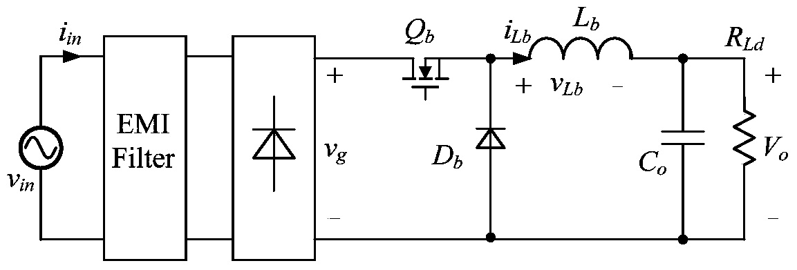
[0026] figure 1 It is the main circuit of the Buck PFC converter.

[0027] For the convenience of analysis, the following assumptions are first made: 1. All devices are ideal components; 2. The output voltage ripple is very small compared with its DC value; 3. The switching frequency is much higher than the input voltage frequency.

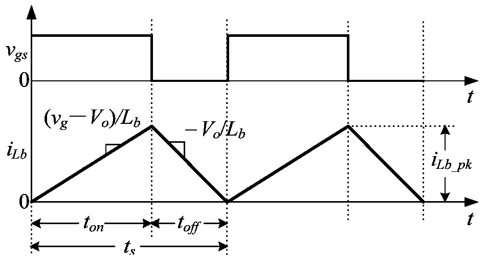
[0028] figure 2 The inductor current waveform in one switching cycle when CRM is given. When Q b When turned on, D b cutoff, the boost inductor L b The voltage across it is v g -V o , its current i Lb Start with zero and start with (v g -V o ) / L b The slope increases linearly. When Q b When shutting down, i Lb by D b freewheeling, at this time L b The voltage across it is v o , i Lb with V o / L b the slope of the drop. Since the...


PUM


Abstract

Disclosed in the invention is a high-power-factor CRM Buck PFC converter comprising a main power circuit, an CRM control and drive circuit, an input voltage feedforward circuit, two multiplying units, and output voltage feedback circuit. The input voltage feedforward circuit is as follows: an output terminal of a voltage-dividing following circuit is connected with a vy of a first multiplying unit and an input terminal of a peak value sampling power unit; an output terminal of the peak value sampling power unit is connected with a vz of the first multiplying unit; a vx of the first multiplying unit is connected with an output terminal of a voltage dividing circuit; an output terminal of the first multiplying unit is connected with one input terminal of a first subtraction circuit; two input terminals of a summing circuit are connected with the output terminals of the voltage-dividing following circuit and the voltage dividing circuit; an output terminal of the summing circuit is connected with the other input terminal of the first subtraction circuit; two input terminals of a third subtraction circuit is connected with the output terminals of the voltage-dividing following circuit and the voltage dividing circuit; and three input terminals of a second multiplying unit are connected with output terminals of the first subtraction circuit, the voltage dividing circuit, and the third subtraction circuit. According to the invention, with introduction of the voltage feedforward circuit, improvement of the power factor of the CRM Buck PFC converter is realized.

Description

technical field [0001] The invention relates to the field of AC-DC converters of electric energy conversion devices, in particular to a CRMBuck PFC converter with high power factor. Background technique [0002] A power factor correction (Power Factor Correction, PFC) converter can reduce input current harmonics and improve input power factor, and has been widely used. PFC converters are divided into active and passive methods. Compared with passive methods, the active method has the advantages of high input power factor, small size, and low cost. [0003] Active PFC converters can adopt a variety of circuit extension and control methods, among which Buck PFC converter is one of several commonly used PFC converters. According to whether the inductor current is continuous or not, it can be divided into three operating modes, namely, inductor current Current continuous mode (Continuous Current Mode, CCM), inductor current critical continuous mode (Critical Continuous Current ...

Claims


Application Information

Patent Timeline
Patent Type & Authority Patents(China)
IPC IPC(8): H02M1/42H02M1/12
CPCY02B70/10
Inventor 王小平姚凯李辉王祎周旭峰
Owner NANJING UNIV OF SCI & TECH
Features
  • R&D
  • Intellectual Property
  • Life Sciences
  • Materials
  • Tech Scout
  • Unparalleled Data Quality
  • Higher Quality Content
  • 60% Fewer Hallucinations
Learn More