
Strip tilling system

A farming system, ribbon technology, applied in farming implements, general control systems, control/regulation systems, etc., to solve problems such as unsatisfactory, lack of flexibility in the system, and reduced speed of farming operations

Active Publication Date: 2015-12-16
KVERNELAND GRP LES LANDES GENUSSON
View PDF3 Cites 1 Cited by
  • Summary
  • Abstract
  • Description
  • Claims
  • Application Information

AI Technical Summary

Problems solved by technology

But this adjustment is not satisfactory because the farmer has to stop the traction unit while adjusting the setting, reducing the speed of the tillage operation
Additionally, existing systems often lack flexibility when selecting the appropriate location for each delivery tube
The inventors have found that this problem is exacerbated when the position of the teeth is adjustable relative to the support frame

Method used


Image

  • Strip tilling system
  • Strip tilling system
  • Strip tilling system

Examples


Embodiment Construction

[0061] Figure 4 to Figure 8 A strip tillage device 11 according to a first embodiment of the invention is shown. The apparatus 11 comprises: at least one tillage unit (commonly referred to as a "set") 13, each set 13 including adjustable teeth 15; and a control system 17 for adjusting each tooth 15 relative to its corresponding set. 13 positions.

[0062] The arrangement of one set 13 will be described in more detail below, which description is applicable to each set 13 (six shown).

[0063] Cover set 13 comprises support frame 19 (see Figure 5 with Figure 7 ). The support frame 19 includes a first support member 19a and a second support member 19b. The first support member 19a and the second support member 19b are disposed substantially parallel to and spaced apart from each other. The tooth 15 is mounted on the support frame 19 between the first support member 19a and the second support member 19b in such a way that the control system 17 can adjust the position of t...


PUM


Abstract

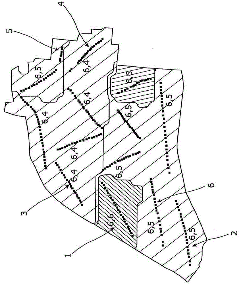
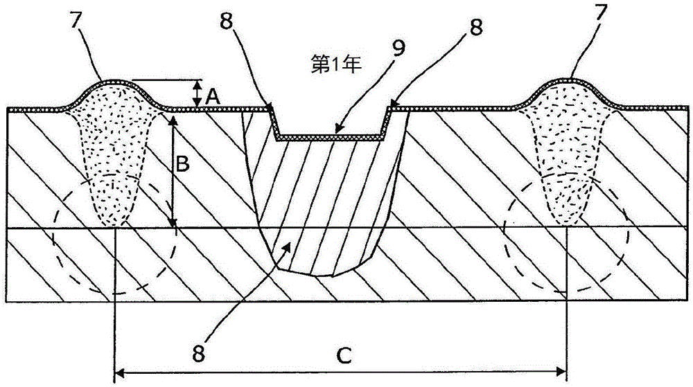
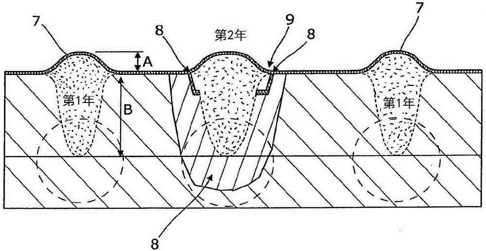
A strip tilling system. The strip tilling system includes: at least one strip tilling unit (13) having a support frame (19) and a tilling member (15) mounted to the support frame (19); a positioning system (39); map data (41) relating to a field to be tilled, said map data (41) including data identifying areas of compacted ground in the field; and a control system (17) for adjusting the position of the tilling member (15) with respect to the support frame (19), wherein said control system (17) is arranged to receive signals from the control system (17), to access the map data (41), and to automatically adjust the position of the tilling member (15) with respect to the support frame (19) when the control system (17) determines that the tilling member (15) is located at an area of compacted ground. A method for strip tilling is also provided.

Description

technical field [0001] The present invention relates to a strip tillage system and a method for strip tillage. Background technique [0002] For farmers, it is necessary to till their fields in order to sow seeds. In recent years, farmers have begun to till their fields in strips, rather than the entire field. Strip tillage is a conservation system that uses minimal tillage, whereby the farmer works only in strips of the field, stirring up only those parts of the field that receive the seeds. The strips are typically about 5 cm to 25 cm wide, spaced apart from each other and arranged substantially parallel. [0003] To strip till a field, a farmer employs a traction unit to drag the strip tillage equipment across the field. Ribbon tillage equipment typically includes an assembly having a plurality of ribbon tillage sets attached to a beam, with the sets being spaced apart along the beam. Each set includes a tine and / or other soil handling device, such as a cutting wheel....

Claims


Application Information

Patent Timeline
IPC IPC(8): A01B37/00A01B63/24A01B79/00
CPCA01B37/00A01B63/24A01B79/005A01B33/00A01B33/087G05B15/02G05D3/00
Inventor G·虎林
Owner KVERNELAND GRP LES LANDES GENUSSON
Learn More