
Device and method for applying tensile force in rolling process of ultra-thin metal strip

A technology of rolling process and application device, which is applied in the direction of metal rolling, metal rolling, rolling mill control device, etc., can solve problems such as broken strips, and achieve the effect of improving production efficiency

Active Publication Date: 2015-12-23
NORTHEASTERN UNIV
View PDF5 Cites 0 Cited by
  • Summary
  • Abstract
  • Description
  • Claims
  • Application Information

AI Technical Summary

Problems solved by technology

Therefore, when the rolled piece is thinned to a certain thickness, it is easy to cause strip breakage due to excessive back tension, forcing the rolling process to terminate

Method used


Image

  • Device and method for applying tensile force in rolling process of ultra-thin metal strip
  • Device and method for applying tensile force in rolling process of ultra-thin metal strip
  • Device and method for applying tensile force in rolling process of ultra-thin metal strip

Examples


Embodiment Construction

[0035] The present invention will be further described in detail below in conjunction with the accompanying drawings and specific embodiments.

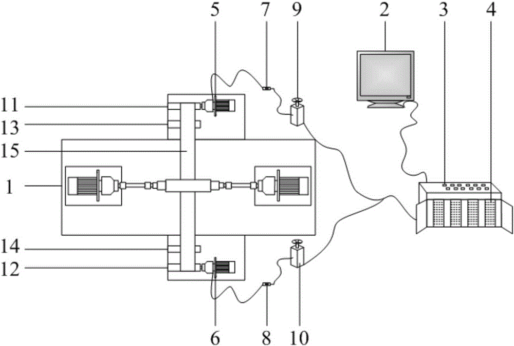
[0036] Such as figure 1 As shown, a tension applying device in a metal extremely thin strip rolling process includes a main control computer 2, an operating console 3, a PLC 4, a first torque motor 5, a second torque motor 6, a first reversing switch 7, a second A reversing switch 8, a first transformer 9 and a second transformer 10; a tension control system man-machine interface is arranged in the main control computer 2, and the main control computer 2 is connected with the console 3 through PLC4, and on the console 3 A rolling forward start switch and a rolling reverse start switch are respectively provided; the PLC4 is connected to the control terminal of the first torque motor 5 through the frequency converter, the first transformer 9, and the first reversing switch 7 in turn; All the way through the frequency converter, the se...


PUM


Abstract

The invention relates to a device and method for applying tensile force in the rolling process of an ultra-thin metal strip. A reversing switch is arranged between a torque motor and a transformer. Before rolling, when the measured value of the inlet thickness of a rolled piece is larger than a set value, namely when the thickness of the rolled piece is large, the mechanical resistance of a transmission system of a rolling mill is smaller than back tensile force under the condition of the thickness, the reversing switch is not turned on to a reversing position, a back tensile force motor carries out conventional forward rotation after being powered on, and the back tensile force is equal to the sum of the mechanical resistance of the transmission system of the rolling mill and tensile force output by the back tensile force motor at the moment. When the measured value of the inlet thickness of the rolled piece is smaller than the set value, namely when the thickness of the rolled piece is small, the mechanical resistance of the transmission system of the rolling mill is larger than the back tensile force under the condition of the thickness the reversing switch is turned on to the reversing position, the back tensile force motor carries out backward rotation after being powered on, and the back tensile force is equal to the difference between the mechanical resistance of the transmission system of the rolling mill and tensile force output by the back tensile force motor at the moment. Thus, the purpose of starting the back tensile force from zero is achieved. Besides, the back tensile force is continuously adjustable in the whole course, so that the phenomenon of strip breakage is avoided effectively.

Description

technical field [0001] The invention belongs to the technical field of ultra-thin strip rolling, in particular to a device and method for applying tension during the ultra-thin metal strip rolling process. Background technique [0002] In recent years, with the rapid development of micro-manufacturing technology and micro-forming technology, the demand for ultra-thin strips of metals, alloys and metal matrix composites is increasing. These ultra-thin strips have been widely used in the microelectronics industry, micro-manufacturing industry, Instrumentation industry and micro-electromechanical industry, etc. [0003] The ultra-thin strips of metals, alloys and metal-based composite materials are mostly obtained by strip tension rolling, and the appropriate tension is not only conducive to the thinning of rolled pieces, but also to the improvement of production efficiency, and is also the key to ensure the shape of ultra-thin strips. Important means, therefore, precise tensi...

Claims


Application Information

Patent Timeline
IPC IPC(8): B21B1/40B21B37/52B21B37/18
Inventor 刘相华孙祥坤宋孟祁俊龙冯禄赵阳
Owner NORTHEASTERN UNIV
Learn More