A new compound broach

A new type of tie rod technology, applied in the direction of broach, broaching machine, metal processing equipment, etc., can solve the problem of unfinished, and achieve the effect of improving the vertical part, improving the work efficiency, and improving the verticality of the upper and lower parts.

Active Publication Date: 2017-08-25
ZHEJIANG ZHUJI CONSTR CHAIN MFG
View PDF7 Cites 0 Cited by
  • Summary
  • Abstract
  • Description
  • Claims
  • Application Information

AI Technical Summary

Problems solved by technology

Although this solution can improve the production efficiency of the broach, the applicant did not complete all the improvement tests when the application date of the utility model was submitted. Need for improvement

Method used


Image

  • A new compound broach
  • A new compound broach
  • A new compound broach

Examples


Embodiment 1

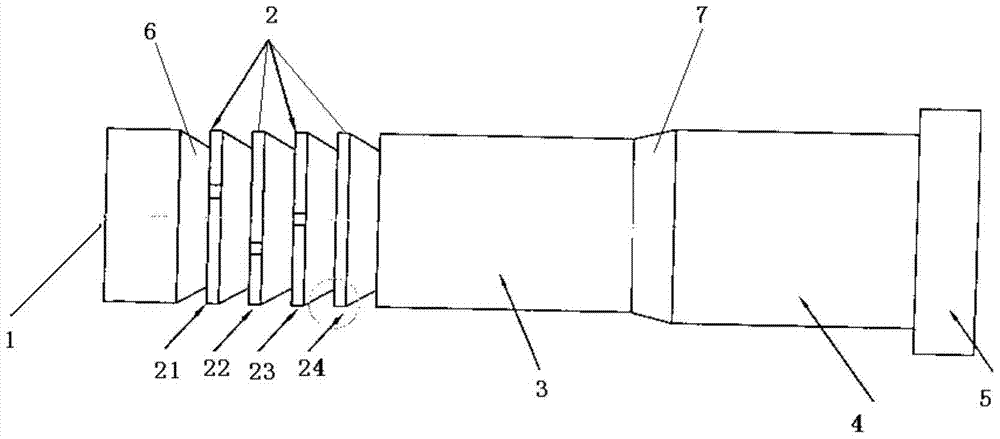
[0028] like figure 1 As shown: the composite broach of the present invention includes a punching nail 1, a tooth 2, a pull rod 3, a broach positioning part 4 and a broach tail 5, and a diameter from the punching nail is set between the punching nail 1 and the tooth 2 1. The first circular frustum connection part 6 that tapers toward the direction of the tooth 2. A second circular frustum connection whose diameter becomes larger from the pull rod 3 to the broach positioning part 4 is provided between the pull rod 3 and the broach positioning part 4. part 7, the pull rod 3 is arranged between the tooth 2 and the second round table connection part 7, the broach positioning part 4 is arranged between the second round table connection part 7 and the broach tail part 5, and the tooth 2 includes a diameter larger than the punching hole The punching teeth with an initial diameter smaller than the punching target diameter and the repairing teeth with a diameter equal to the punching ta...

Embodiment 2

[0043] As a preferred embodiment, figure 1 The compound broach shown has four teeth, that is, the tooth 2 includes a first tooth 21, a second tooth 22, a third tooth 23 and a fourth tooth 24, wherein the first tooth 21 and the second tooth 22 are punching teeth, The third tooth 23 and the fourth tooth 24 are repairing teeth, wherein the diameter of the first tooth is 0.1mm-0.15mm larger than the diameter of the punching nail, and the diameter of the second tooth is 0.1mm-0.1mm larger than the diameter of the first tooth. 0.15mm, the diameter of the punching nail 1 is equal to the initial diameter of the punching hole. In this embodiment, the processing from the initial parameters of the punching to the target parameters is completed by three broaching of the punching nail 1, the first tooth 21 and the second tooth 22, and then the hole repair is realized by the third tooth 23 and the fourth tooth 24, Further improve the up and down verticality of the punched inner hole cylind...

Embodiment 3

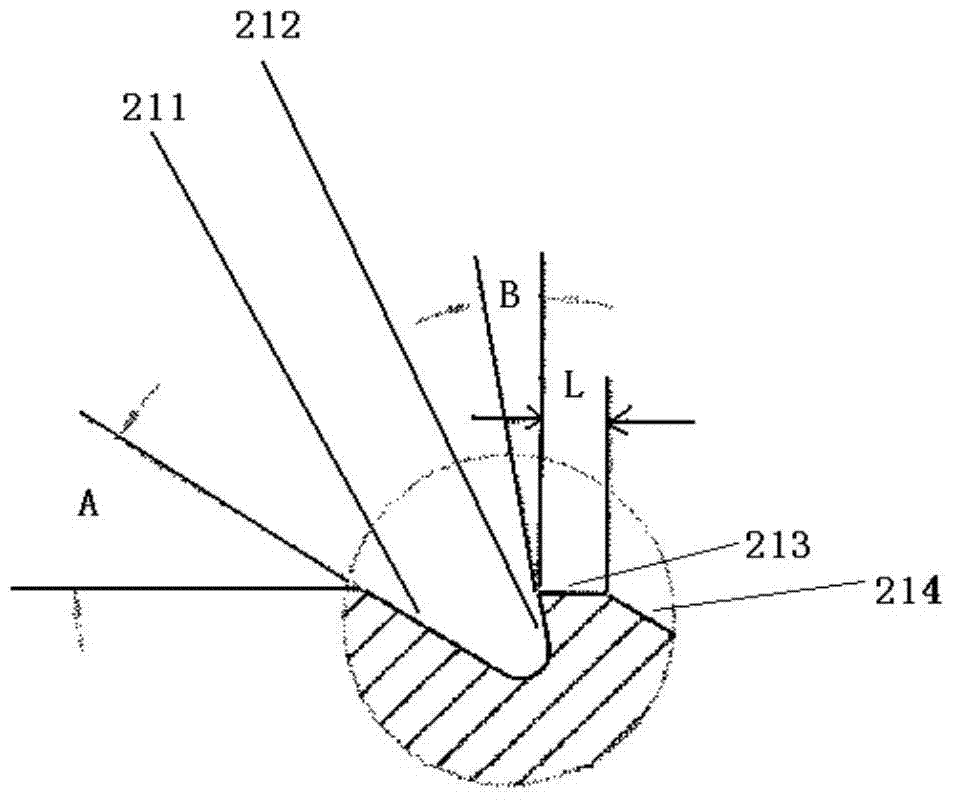
[0049] like figure 2 As shown, the punching tooth and the repairing tooth both include a first base surface 211, a second base surface 212, a third base surface 213 and a fourth base surface 214, wherein the distance between the first base surface 211 and the horizontal plane The included angle is A, the included angle between the second base surface 212 and the vertical surface is B, the horizontal plane and the vertical surface are perpendicular to each other, and the first base surface 211 and the second base surface 212 are smoothly connected by an arc surface, A groove is formed at the arc-shaped surface between the first base surface 211 and the second base surface 212; the second base surface 212 and the third base surface 213 form tooth tips at the intersection; the width of the third base surface 213 is L , the fourth base surface 214 is inclined downward from the third base surface 213 at a position whose distance from the tooth tip is equal to the width of the thir...


PUM


Abstract

The invention discloses a novel compound broach, comprising: a punch nail, a tooth, a pull rod, a broach positioning part and a broach tail. The first circular platform connection part, the second circular platform connection part is arranged between the pull rod and the broach positioning part, the broach positioning part is arranged between the second circular platform connection part and the broach tail, and the teeth include diameters punching teeth larger than the initial diameter of punching and smaller than the punching target diameter and repairing teeth with a diameter equal to the punching target diameter, the punching teeth are closer to the punching nail than the repairing teeth, the The diameter of the punching nail is equal to the initial diameter of the punching hole. Compared with the existing technology, this new compound broach saves the time spent on the second process of mold installation, test mode and tooling, and at the same time solves the technical problem that the positioning of the second hole repairing process is difficult to determine in the prior art. " The bright band "that is, the vertical portion of the inner wall of the punched hole's aperture is raised.

Description

technical field [0001] The invention relates to a novel composite broach, which belongs to the technical field of bending plate chain processing. Background technique [0002] The chain plates of non-standard chains, large-size 40A, standard roller chains above B and various heavy-duty curved plate chains need to be punched during the production process, so that the inner and outer chain plates are processed to form the required aperture. The existing processing process on the chain plate is to punch the nails first, and punch the chain plate through the stamping equipment. After punching the chain plate with the punching nails, the upper and lower ends of the inner diameter of the hole must not be vertical. The reason is that The cooperation between the punching nail and the die is based on the traditional method. The inner hole parameters of the die must be enlarged by about 0.3 to 0.5 mm on the basis of the punching nail parameters. It depends on the thickness of the chai...

Claims


Application Information

Patent Timeline
Patent Type & Authority Patents(China)
IPC IPC(8): B23D43/00
Inventor 宣国建
Owner ZHEJIANG ZHUJI CONSTR CHAIN MFG
Why Eureka
Try Eureka