Method for manufacturing fluid bearing and fluid bearing manufactured by the method

a technology of fluid bearings and manufacturing methods, which is applied in the direction of sliding contact bearings, manufacturing tools, electrical-based machining electrodes, etc., can solve the problems of affecting performance, difficult to obtain a highly accurate perpendicularity between radial and thrust bearings, and difficult to maintain optimal spaces between shafts and radial bearings, so as to achieve high perpendicularity and reduce cost. , the effect of high roundness

Inactive Publication Date: 2002-09-12
SANKYO SEIKI MFG CO LTD
View PDF0 Cites 17 Cited by
  • Summary
  • Abstract
  • Description
  • Claims
  • Application Information

AI Technical Summary

Benefits of technology

[0013] As a result, the fluid bearing grooves can be simultaneously formed at at least two places, and more preferably, at two places, through electrolytic machining on the inner surface of the work piece facing each of the groove sets provided in the mask member. Accordingly, at least two radial bearings or a thrust bearing and a radial bearing can be formed in a unitary structure, which allows the manufacture of fluid bearings with superior perpendicularity and greatly improved quality.
[0025] In accordance with the present invention, the groove sets consisting of multiple grooves are located at two places along the axial direction of the rotary shaft and the two groove sets form an angle .theta., where the angle .theta. is in the range of 0.degree..ltoreq..theta..ltoreq.90.degree., and the cross-sectional shape of each of the grooves is rectangular. As a result, a fluid bearing with different sets of bearings, such as, for example, two radial bearings, a set of thrust and radial bearings or the like, can be readily manufactured by changing the angle .theta.(0.degree..ltoreq.90.degree.).

Problems solved by technology

As a result, in a conventional fluid bearing such as the one described above, separate structures for the radial bearing and the thrust bearing make it difficult to obtain a highly accurate perpendicularity between the radial and thrust bearings; and the lack of perpendicularity have an impact on the performance of the motor itself.
Furthermore, because the radial bearing and the thrust bearing have separate structures, it is difficult to maintain optimal spaces both between the shaft and the radial bearing and between the shaft and the thrust bearing.
This consequently makes it difficult to maintain a balance between the radial force and the thrust force.
Moreover, the conventional fluid bearing is likely to lack in press-fit strength between the thrust plate 4 and the shaft 1.
On the other hand, when the press-fit strength is increased, problems such as stress fatigue and destruction likely occur.
In addition, the separate structures for radial and thrust bearings result in a large number of parts, and numerous process steps in the assembly that require high precision, such as press-fitting the shaft 1 and the like, which cause increased cost.

Method used


Image

  • Method for manufacturing fluid bearing and fluid bearing manufactured by the method
  • Method for manufacturing fluid bearing and fluid bearing manufactured by the method
  • Method for manufacturing fluid bearing and fluid bearing manufactured by the method

Examples


Embodiment Construction

[0038] Embodiments of fluid bearing manufacturing methods and of fluid bearings manufactured by the methods are described below with reference tot he accompanying drawings.

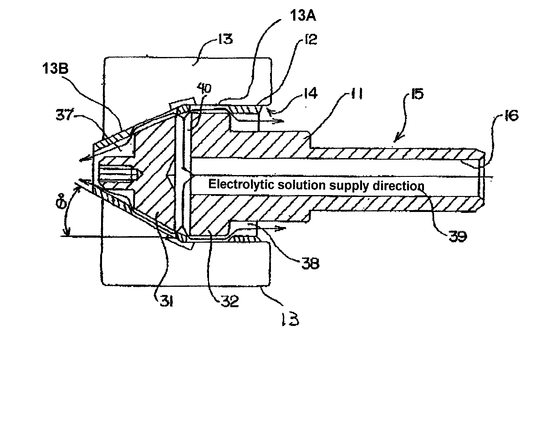
[0039] In the embodiments described below, a fluid bearing has two bearings with dynamic pressure generating grooves, such as a thrust bearing and a radial bearing, formed as a single part in a unitary structure. The two bearings may be provided on a sleeve section, i.e., a bearing, or on a rotary shaft. FIG. 1 shows an example of a method of manufacturing a fluid bearing in which dynamic pressure generating grooves for both the thrust bearing and radial bearing are formed.

[0040] FIG. 1 shows a work piece 13 (i.e., a sleeve, in other words, a bearing) in which grooves are to be formed on the inside of the work piece 13 by a fluid bearing manufacturing tool 15. The work piece 13 is provided with a bore 14 at a center thereof. The fluid bearing manufacturing tool 15 is inserted in the bore 14 and a power source for ...


PUM

PropertyMeasurementUnit
angleaaaaaaaaaa
angleaaaaaaaaaa
circumferenceaaaaaaaaaa

Abstract

A method for manufacturing a fluid bearing is provided. A mask member having at least two sets of grooves provided at least two places along an axial direction is affixed to an outer surface of an electrode section of a fluid bearing manufacturing tool. Each of the groove sets consists of multiple grooves in a shape corresponding to designed fluid bearing grooves on a work piece, such as, for example, a sleeve section of the fluid bearing. The fluid bearing manufacturing tool is inserted into a hole created in the work piece, wherein a power source for electrolytic machining is connected between the fluid bearing manufacturing tool and the work piece. An electrolytic solution between the manufacturing tool and the work piece is allowed to flow to form fluid bearing grooves on an inner surface of the work piece through electrolytic machining.

Description

[0001] 1. Field of the Invention[0002] The present invention relates to a method for manufacturing a fluid bearing with two bearings, such as a thrust bearing and a radial bearing, and to a fluid bearing manufactured by the method.[0003] 2. Description of Related Art[0004] FIG. 11 shows an example of a conventional fluid bearing. As shown in the figure, a shaft 1 with grooves la for generating radial dynamic pressure is inserted into an inner hole of a bearing 2. The bottom end of the shaft 1 is press-fitted in a thrust plate 4 that is provided with thrust dynamic pressure bearing grooves 4a and 4b at its top and bottom surfaces. The thrust plate 4 is interposed between a counter plate 5 situated under the shaft 1 and the bearing 2. The counter plate 5 is fixed to the bearing 2 with an adhesive to seal the bearing 2 to complete a bearing assembly.[0005] A radial dynamic pressure bearing 3 is formed between the shaft 1 and the bearing 2, and the dynamic pressure bearing works to supp...

Claims


Application Information

Patent Timeline
Patent Type & Authority Applications(United States)
IPC IPC(8): F16C33/14B23H3/04B23H1/04F16C17/10F16C33/10B23H9/00
CPCB23H1/04B23H9/00B23H2200/10F16C17/026F16C33/14F16C33/107Y10T29/49639F16C17/105F16C17/102
Inventor USUI, MOTONORI
Owner SANKYO SEIKI MFG CO LTD
Why Eureka
Try Eureka