
Vehicle

A vehicle and condensation tank technology, applied in the field of vehicles, can solve problems such as no consideration

Active Publication Date: 2015-12-23
MITSUBISHI MOTORS CORP +1
View PDF5 Cites 0 Cited by
  • Summary
  • Abstract
  • Description
  • Claims
  • Application Information

AI Technical Summary

Problems solved by technology

This device pays attention to the amount of expansion and deformation of the tank, and does not consider the influence of the air staying around the low-temperature tank on the refrigerant and the influence of the air flowing around the high-temperature tank on the heat medium (for example, refer to patent documents 1)

Method used


Image

  • Vehicle
  • Vehicle
  • Vehicle

Examples


Embodiment approach 1

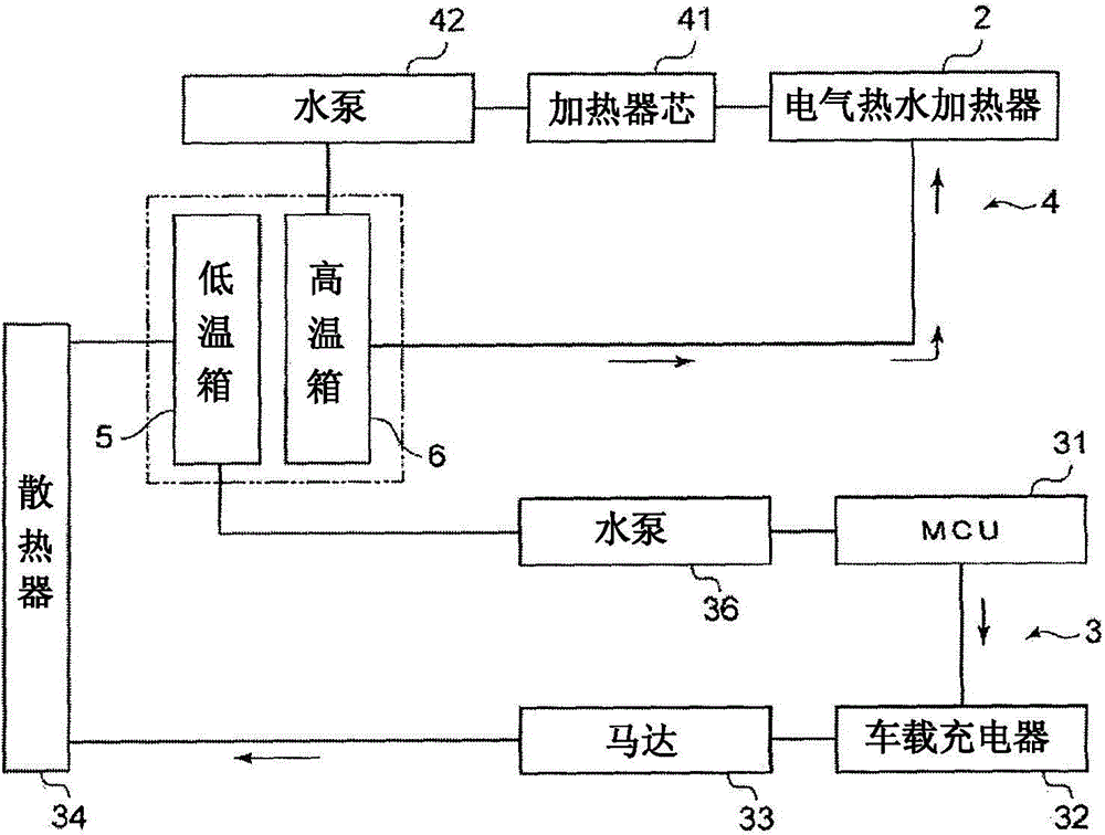
[0074] figure 2 It is a schematic diagram showing a cooling water circulation channel through which cooling water flows and a hot water circulation channel through which hot water flows.

[0075] Such as figure 2 As shown, the cooling water circulation flow path 3 is used to cool the heat-generating vehicle components such as the microcontroller unit (MCU) 31 , the on-board charger (OBC) 32 , the motor (motor) 33 , and the like. A microcontroller unit 31 , an on-board charger 32 , a motor 33 , a radiator 34 , a low temperature tank (condenser tank) 5 , and a water pump 36 are provided in the cooling water circulation flow path 3 . The cooling water (refrigerant) flowing through the cooling water circulation channel 3 is supplied to the water pump 36 through the low temperature tank 5 from the radiator 34 . Then, the cooling water drawn by the water pump 36 flows in the order of the microcontroller unit 31 , the on-board charger 32 , and the motor 33 , and returns to the ra...

Embodiment approach 2

[0090] The cooling water circulation flow path and the hot water circulation flow path of the electric vehicle according to Embodiment 2 have the same configuration as that of Embodiment 1 described above, and therefore, citing figure 2 to explain. In addition, the same code|symbol is attached|subjected and demonstrated about the structure similar to Embodiment 1 mentioned above.

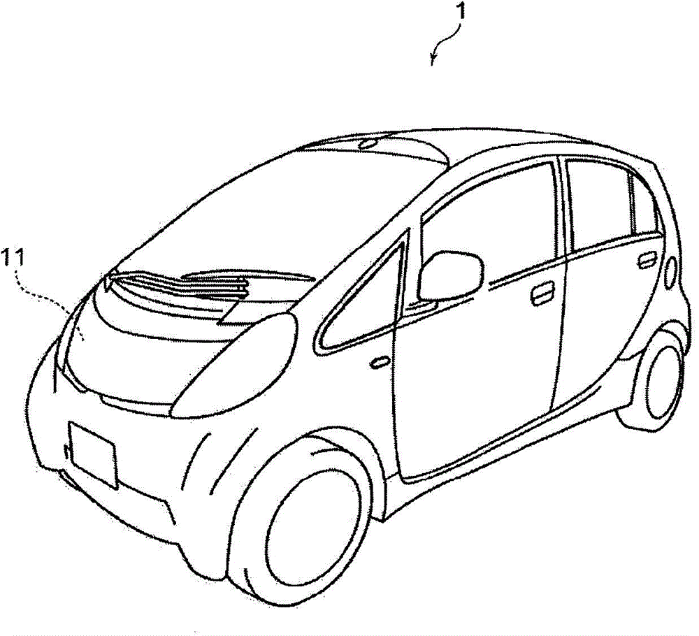
[0091] Such as figure 2 As shown, the electric vehicle 1 according to Embodiment 2 of the present invention integrates the low-temperature tank 7 arranged in the cooling water circulation flow path 3 and the high-temperature box 8 arranged in the hot water circulation flow path 4 to form a condenser box 9 ( Integral condenser box) (refer to Figure 7 ).

[0092] The cooling water circulation flow path 3 is used to cool in-vehicle components that generate heat, such as a microcontroller unit (MCU) 31 , an on-board charger (OBC) 32 , a motor (motor) 33 , and the like. The cooling water circulati...


PUM


Abstract

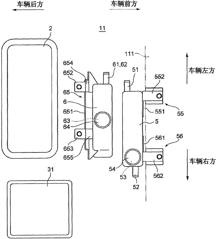
The invention provides a vehicle, which can inhibit that a cooling agent can be heated by retention air around a low temperature box and can inhibit that a thermal medium can be cooled by air around a high temperature box. A vehicle which uses hot water heated by an electric hot water heater (2) to heat air in a carriage, includes: a cooling water circular flow path where cooling water cooled by car parts such as a micro control unit (31) cycles; the low temperature box (5) formed on the cooling water circular flow path; a hot water circular flow path where hot water heated by the electric hot water heater (2) cycles; the high temperature box formed on the hot water circular flow path; the high temperature box is positioned in the rear side of forward and backward directions of the vehicle of the low temperature box and the high temperature box (6) and the low temperature box (5) have a space and are juxtaposed; the electric hot water heater (2) is juxtaposed in the rear side of forward and backward directions of the vehicle of the high temperature box.

Description

technical field [0001] The present invention relates to a vehicle, and more specifically, to a vehicle in which air in a vehicle compartment is heated by a heat medium heated by a heating device such as an electric hot water heater. Background technique [0002] In vehicles, particularly electric vehicles, the air in the cabin is generally heated by a heat medium heated by a heating device such as an electric hot water heater. The electric vehicle includes: a refrigerant condensing tank (hereinafter referred to as "low temperature tank"), which is installed in a refrigerant circulation flow path through which refrigerant for cooling vehicle components circulates; and a heat medium condensing tank (Hereinbelow, referred to as "high temperature tank") is installed in a heat medium circulation channel through which a heat medium heated by a heating device circulates. Then, the low-temperature refrigerant flows through the low temperature tank, and the air contained in the refr...

Claims


Application Information

Patent Timeline
Patent Type & Authority Applications(China)
IPC IPC(8): B60H1/22B60K11/02
CPCB60H1/2221B60K11/02
Inventor 石川清贵西尾善明汤谷和久
Owner MITSUBISHI MOTORS CORP
Learn More