Wireless sensor network route method based on artificial potential field

A wireless sensor and artificial potential field technology, applied in the field of communication, can solve the problems of complex calculation methods, a large amount of routing overhead, and high energy consumption

Active Publication Date: 2014-07-02
韩小学
View PDF2 Cites 11 Cited by
  • Summary
  • Abstract
  • Description
  • Claims
  • Application Information

AI Technical Summary

Problems solved by technology

The wireless sensor network routing method introduced in the literature has the following problems: the use of global map information when calculating the shortest path requires a large amount of routin

Method used


Image

  • Wireless sensor network route method based on artificial potential field
  • Wireless sensor network route method based on artificial potential field
  • Wireless sensor network route method based on artificial potential field

Examples


Embodiment Construction

[0053] Now in conjunction with embodiment, accompanying drawing, the present invention will be further described:

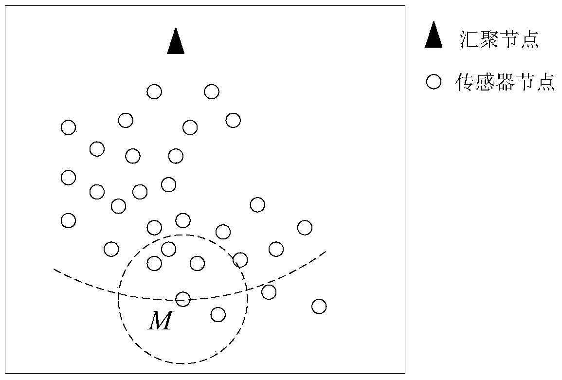
[0054] figure 1 is a typical network topology, where the dotted circle centered on node M represents the wireless communication radius of node M. The center of the arc passing through node M is the sink node, and the radius is the distance from M to the sink node. Follow the steps below to initialize:

[0055] a) Encode the sink nodes in the network and set their ID equal to 1; encode the sensor nodes in the network so that their IDs are different from each other and not equal to 1, and then all sensor nodes initialize their empty flags is "false";

[0056] b) The sensor node obtains its own position coordinates P through the positioning device i (x i ,y i ), where x i 、y i The horizontal and vertical coordinate values ​​of their location points respectively; the sensor node reads its own remaining power V through the power management module i ;

[0057...


PUM


Abstract

The invention relates to a wireless sensor network route method based on an artificial potential field. The wireless sensor network route method includes the four steps of initializing, route building, route uploading and data transmitting. The problems that in the prior art, the route cost and the route energy consumption are large, and route selection does not have the load balancing function are solved, the calculation complexity is lowered, a large amount of route cost is avoided, the energy efficiency is improved, and the network load balancing function can be achieved.

Description

technical field [0001] The invention relates to the communication field, in particular to a wireless sensor network routing method based on an artificial potential field. Background technique [0002] Wireless sensor networks have the advantages of flexible deployment, convenient expansion, and low price. However, sensor nodes are generally powered by batteries, so energy is a key issue affecting the performance of wireless sensor networks. Routing is a method of selecting the forwarding path of a data packet from a source node to a destination node, and determining how the data packet is forwarded along the path. Routing methods for wireless sensor networks require special attention to energy-saving features. The concept of artificial potential field was first proposed by Khatib in the document "Real-time obstacle avoidance for manipulators and mobile robots [J]. The international journal of robotics research, 1986, 5(1): 90-98", which was applied to soccer robot avoidanc...

Claims


Application Information

Patent Timeline
IPC IPC(8): H04W40/04H04W40/10H04W84/18
CPCY02B60/50Y02D30/70
Inventor 张若南王世超蔡琳
Owner 韩小学
Why Eureka
Try Eureka