Supercharge Your Innovation With Domain-Expert AI Agents!

Method of operating an electromechanical vehicle braking system

A technology of vehicle braking and wheel brakes, which is applied in the direction of brakes, vehicle components, braking transmissions, etc., and can solve problems such as rear-end collisions and unfavorable extension of braking distances

Active Publication Date: 2019-04-23
FORD GLOBAL TECH LLC
View PDF4 Cites 0 Cited by
  • Summary
  • Abstract
  • Description
  • Claims
  • Application Information

AI Technical Summary

Problems solved by technology

This leads to an unfavorable prolongation of the braking distance, which can lead, for example, to rear-end collisions

Method used


Image

  • Method of operating an electromechanical vehicle braking system

Examples


Embodiment Construction

[0008] It should be pointed out that the features and measures described individually in the following description can be combined with each other in any technically advantageous manner and disclose additional embodiments of the present invention. Furthermore, the specification describes and illustrates the invention in this respect.

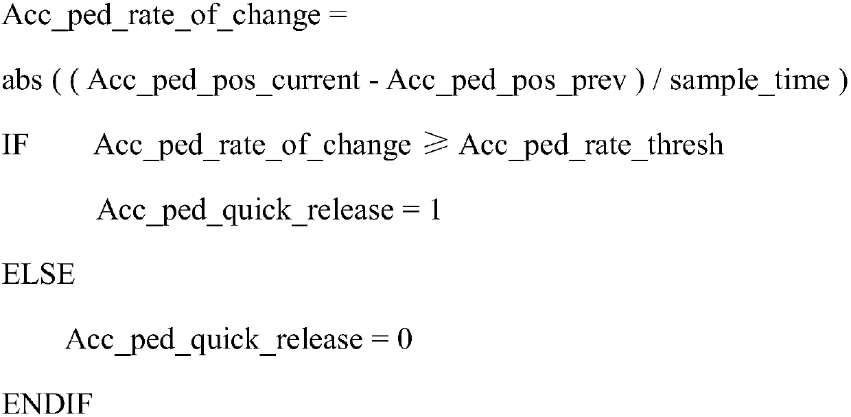
[0009] Accordingly, a method of operating such an electromechanical vehicle braking system is described below. The vehicle braking system comprises an ESP (Electronic Stability Program) module and at least two brake circuits each having two wheel brakes each assigned at least one inlet valve and at least one outlet valve, where each Each brake circuit contains at least one HS valve and at least one US valve and at least one low-pressure storage device. The method according to the invention provides that, prior to a possible braking procedure, a final preload is built up in at least part of the vehicle braking system. The term "final pre-pressu...


PUM


Abstract

The invention relates to a method of operating an electromechanical vehicle braking system comprising an ESP module and at least two brake circuits each having two wheel brakes each assigned at least one inlet valve and at least one outlet valve, wherein each brake circuit contains at least one high-pressure switching valve and one low-pressure switching valve and at least one low-pressure storage device, wherein the final pre-pressure is at least A part is established according to a trigger factor, wherein closing each inlet valve and opening each outlet valve causes the low pressure reservoir to be filled with a first pre-pressure amount of brake fluid, wherein once the first pre-pressure amount has been reached, the ESP pump is activated for filling A vehicle braking system comprising an adjustable final pre-pressure amount dependent on a factor of a low-pressure storage device, wherein all valves are closed if a set final pre-pressure is reached, and wherein the final pre-pressure built up during the occurrence of a braking procedure is at least partly Or at least one wheel brake supplied to the vehicle braking system is supplemented by an additional pressure which depends at least on the intensity of the braking program, wherein at least the inlet valve is opened and the ESP pump generates the additional pressure.

Description

technical field [0001] The invention relates to a method of operating an electromechanical braking system, in particular a vehicle braking system. Background technique [0002] A brake assist system installed in a vehicle assists the person in control of the vehicle, especially during brake application in hazardous or emergency situations. The principle of such a brake assist system is based on evaluating the event of an accident. It has been found that during such an evaluation, the respective possible brake force boosts are actually used only rarely, since the actuation of the foot brake is too weak or too slow. This leads to an unfavorable extension of the braking distance, which can lead, for example, to a rear-end collision. [0003] Conventional brake boosters operate under vacuum conditions. The difference between low pressure and atmospheric pressure is used to generate boost. This boost is used to augment the manually provided driving force so that the actual br...

Claims


Application Information

Patent Timeline
IPC IPC(8): B60T8/17B60T13/66
CPCB60T8/17B60T13/66B60T7/12B60T7/22B60T13/662B60T2201/12B60T8/3275B60T8/4872B60T2201/10B60T8/3255
Inventor 托马斯·斯文森
Owner FORD GLOBAL TECH LLC
Features
  • R&D
  • Intellectual Property
  • Life Sciences
  • Materials
  • Tech Scout
  • Unparalleled Data Quality
  • Higher Quality Content
  • 60% Fewer Hallucinations
Learn More