Method of operating MRI apparatus

A technology of magnets and target frequencies, applied in measuring devices, magnetic resonance measurements, instruments, etc., can solve problems such as frequent service inspections, achieve the effect of extending time intervals and reducing downtime

Active Publication Date: 2020-02-28
SIEMENS HEALTHCARE GMBH
View PDF4 Cites 0 Cited by
  • Summary
  • Abstract
  • Description
  • Claims
  • Application Information

AI Technical Summary

Problems solved by technology

These early low-field vertical systems were known to be less reliable than comparable horizontal-field systems (with cage body coils), necessitating relatively frequent scheduled service inspections

Method used


Image

  • Method of operating MRI apparatus
  • Method of operating MRI apparatus
  • Method of operating MRI apparatus

Examples


Embodiment Construction

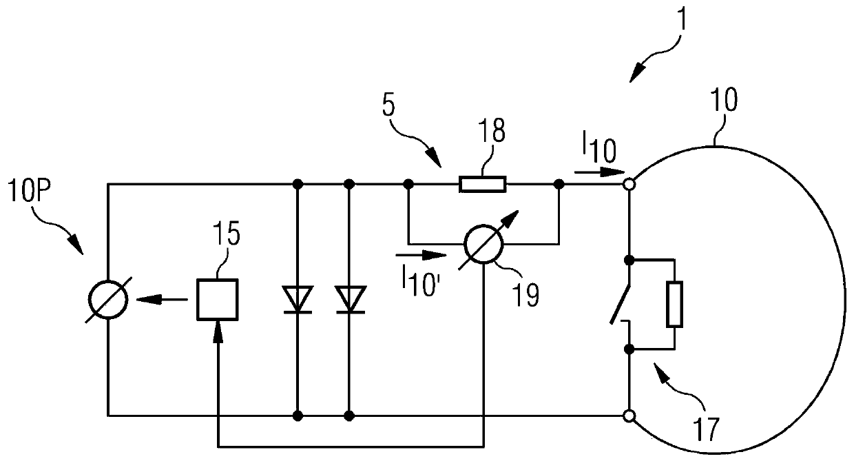
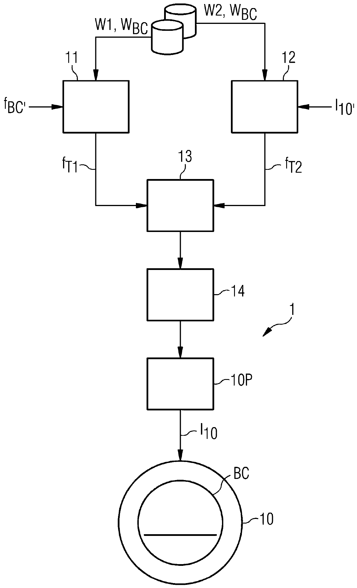
[0037] figure 1 A greatly simplified circuit diagram of a superconducting low-field MRI device 1 is shown. The device comprises a main magnet 10, which generates a very uniform main magnetic field B0. figure 2 A simplified block diagram of the MRI apparatus 1 is shown indicating a main magnet 10 . It can be assumed that there is an additional general arrangement, namely a body coil BC, shim coils and several gradient coils. MPSU 10P is used to supply current I to the magnet 10 during the magnetization process 10 . A switch assembly 17 comprising a superconducting switch in parallel with a shunt resistor is shown connected across the main magnet coil. The switch is closed during magnetization so that a small amount of current flows through the shunt resistor. When the desired magnetic field strength is reached, the switch opens.

[0038] In this exemplary embodiment, the current sensor S is realized as an ammeter shunt and comprises a shunt 18 and an ammeter 19 arranged ...


PUM


Abstract

The invention describes a method of operating an MRI apparatus (1). The method comprises the steps of identifying a first magnet target frequency (fT1) based on a first tolerance window (W1); identifying a second magnet target frequency (fT2) based on the second tolerance window (W2); selecting one of the magnet target frequencies (fT1, fT2); and exciting a magnet (10) of the MRI apparatus (1) tothe selected magnet target frequency (fT1, fT2). The invention further describes an MRI apparatus (1) and a computer program product for carrying out the steps of the method.

Description

technical field [0001] The present invention describes a method of operating an MRI apparatus. The invention further describes an MRI apparatus. Background technique [0002] Developments in the field of magnetic resonance imaging (MRI) systems have led to the advancement of low field systems, which may be preferred due to their smaller footprint. Low-field systems can be open, allow for interventional procedures, and are less expensive. The term "low field system" generally refers to a system having a magnetic field strength of at most 1.0 Tesla. MRI systems with magnetic field strengths in excess of 1.0 Tesla are often referred to as "high field systems". Field strengths of low field systems currently under development can be even lower than 1.0 Tesla, and can even be lower than 0.5 Tesla. [0003] When an MRI system is first installed in the field, a ramp process is performed to establish a main magnetic field (also referred to as a static background field) in the mai...

Claims


Application Information

Patent Timeline
Patent Type & Authority Applications(China)
IPC IPC(8): G01R33/32
CPCG01R33/32G01R33/3802G01R33/381G01R33/445
Inventor S.比伯A.班普顿M.威斯特A.德奥利韦拉V.莫德尔J.尼斯特勒A.波特哈斯特
Owner SIEMENS HEALTHCARE GMBH
Why Eureka
Try Eureka