Time synchronization method of wireless sensor networks

A wireless sensor and time synchronization technology, applied in synchronization devices, network topology, wireless communication and other directions, can solve the problems of high energy consumption, regardless of transmission delay and access delay, oscillator frequency deviation, etc., to reduce node energy. Consumption, reduce algorithm complexity and energy consumption, improve the effect of time interval

Active Publication Date: 2012-08-01
苏州摩多物联科技有限公司
View PDF3 Cites 32 Cited by
  • Summary
  • Abstract
  • Description
  • Claims
  • Application Information

AI Technical Summary

Problems solved by technology

RBS does not consider the transmission delay and access delay to obtain high synchronization accuracy, but the time complexity of the algorithm is high and the energy consumption is high; TPSN even eliminates the uncertainty of the receiving time, and the accuracy can reach hundreds of microseconds, but High energy consumption, suitable for stable networks with high time accuracy requirements; FTPS uses linear regression algorithm to obtain high synchronization accuracy, suitable for military occasions; DMTS sacrifices part of time synchronization accuracy in exchange for lower computational complexity and energy consumption , suitable for systems that do not require high time precision
[0005] However, for a stable network with a fixed topology, its energy consumption and algorithm complexity are strictly limited, and the sensor sub-nodes (slave nodes, Slave Node) in the network need to periodically report to the sink node (master node, Master Node) sends the monitored information, but due to the frequency deviation and drift of the oscillators of each sensor node, the slave node needs to periodically synchronize the time to the master node. Considering the energy consumption requirements of the master node, it should be as possible as possible Reduce the frequency of time synchronization
For this kind of application, the existing typical time synchronization algorithm mentioned above is difficult to satisfy

Method used


Image

  • Time synchronization method of wireless sensor networks
  • Time synchronization method of wireless sensor networks
  • Time synchronization method of wireless sensor networks

Examples


Embodiment Construction

[0035] In order to enable those skilled in the art to better understand the technical solutions in the present application, the technical solutions in the embodiments of the present application will be clearly and completely described below in conjunction with the drawings in the embodiments of the present application. Obviously, the described The embodiments are only some of the embodiments of the present application, but not all of them. Based on the embodiments in this application, all other embodiments obtained by persons of ordinary skill in the art without creative efforts shall fall within the scope of protection of this application.

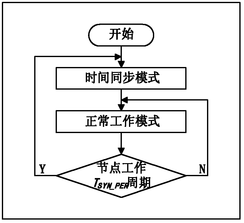
[0036] The embodiment of the present invention discloses a time synchronization method for a wireless sensor network, including:

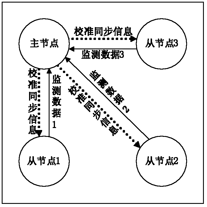
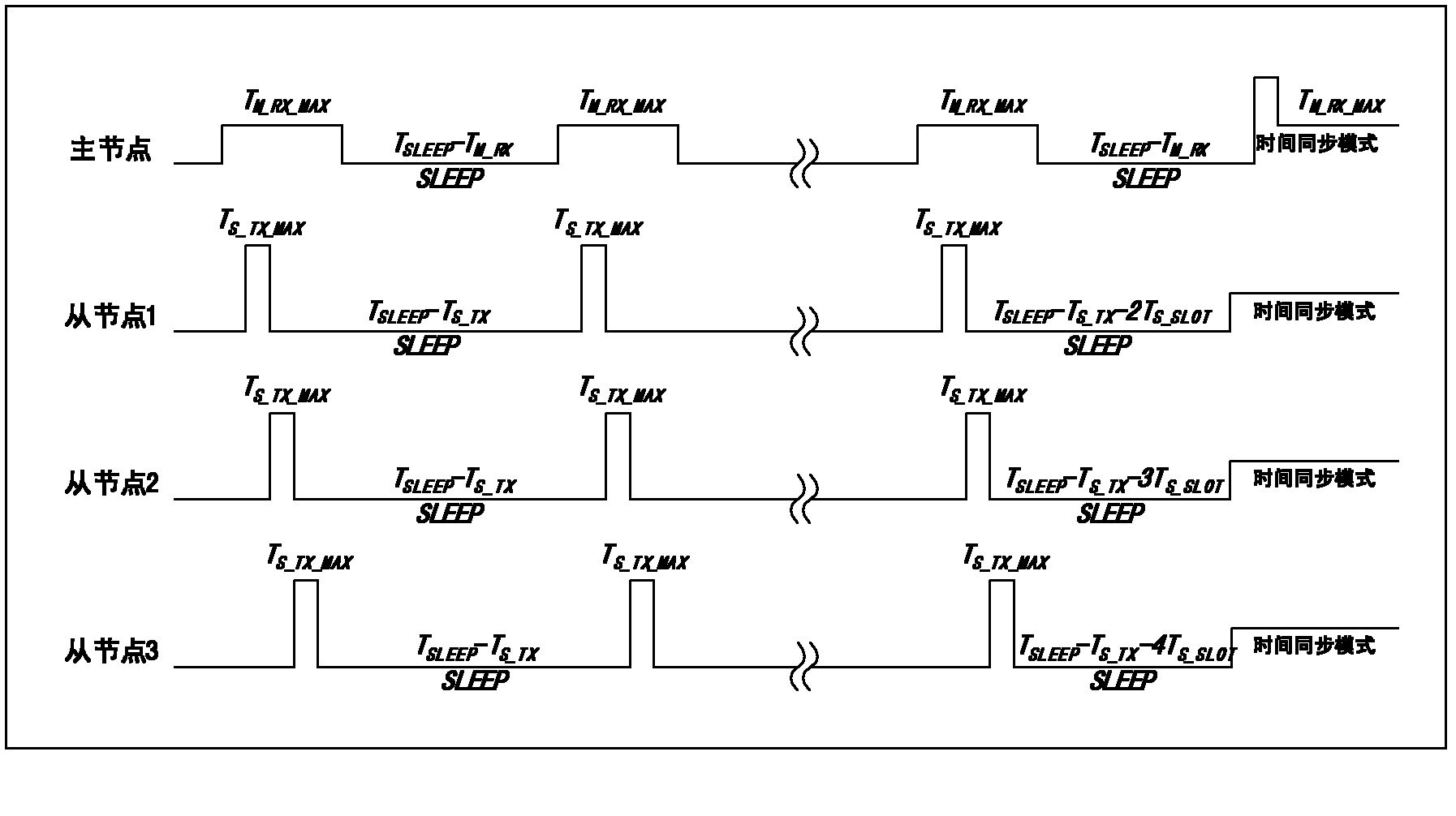
[0037] In normal working mode, the slave node sends monitoring data to the master node in a certain working cycle, and the master node receives and processes data from multiple slave nodes;

[0038] Each node...


PUM


Abstract

The invention discloses a time synchronization method of wireless sensor networks and belongs to the technical field of the wireless sensor networks. According to a technical scheme, a master node receives monitoring data of different slave nodes, counts failure rates of the received data to regulate synchronous cycle time at the same time and counts average time differences of the data of the different slave nodes received in adjacent work periods to calculate step sizes which need to be regulated by slave node clocks; the master node broadcasts calibration synchronous information to the slave nodes after the whole work period is ended; and the slave nodes synchronize own local relative clocks to the master node according to the received information and calibrate own clock counts in the next work periods. Compared with the prior art, the method has the advantages that an extremely-low time complexity algorithm is adopted, so that the time synchronization frequency is greatly reduced, and the energy consumption of the nodes is effectively reduced.

Description

technical field [0001] The invention belongs to the technical field of wireless sensor networks, in particular to a time synchronization method of wireless sensor networks. Background technique [0002] Wireless sensor networks (Wireless Sensor Networks, WSN) are composed of a large number of sensor nodes, usually deployed in unattended monitoring areas, obtain monitoring information in a self-organizing and collaborative manner, and send the processed information to end users, WSN It has been widely used in many fields such as military, industry, agriculture and medical treatment. [0003] In WSN, different nodes have their own local time. Due to the deviation (frequency deviation) of the crystal oscillator frequency of different nodes, and with the change of temperature, voltage, air pressure, etc. and the aging of the oscillator, it will also cause the oscillator The natural frequency of the device drifts (frequency drift). Therefore, the time synchronization mechanism ...

Claims


Application Information

Patent Timeline
Patent Type & Authority Applications(China)
IPC IPC(8): H04W52/02H04W56/00H04W84/18
CPCY02D30/70
Inventor 李鸿韩永朋安勇赵伟光阎跃鹏牟荣增
Owner 苏州摩多物联科技有限公司
Why Eureka
Try Eureka