Device, System, and Method of Reduced-Power Imaging

a technology of reduced power and imaging, applied in the field of imaging and image acquisition, can solve the problems of inefficient power consumption and power consumption, and achieve the effect of reducing power consumption of the camera

Inactive Publication Date: 2008-11-13
PIMA ELECTRONICS SYST
View PDF7 Cites 28 Cited by
  • Summary
  • Abstract
  • Description
  • Claims
  • Application Information

AI Technical Summary

Benefits of technology

[0012]Some embodiments of the invention may allow, for example, reduced power consumption by the camera and/or by...

Problems solved by technology

Some security and surveillance cameras may include, for example, an imager (e.g., a Complementary Metal Oxide Semiconductor (CMOS) imager or a Charge Coupled Device (CCD) imager) which may be continuously operational and may c...

Method used


Image

  • Device, System, and Method of Reduced-Power Imaging
  • Device, System, and Method of Reduced-Power Imaging
  • Device, System, and Method of Reduced-Power Imaging

Examples


Embodiment Construction

[0018]In the following description, various aspects of the invention will be described. For purposes of explanation, specific configurations and details are set forth in order to provide a thorough understanding of the invention. However, it will also be apparent to one skilled in the art that the invention may be practiced without the specific details presented herein. Furthermore, well-known features may be omitted or simplified in order not to obscure the invention.

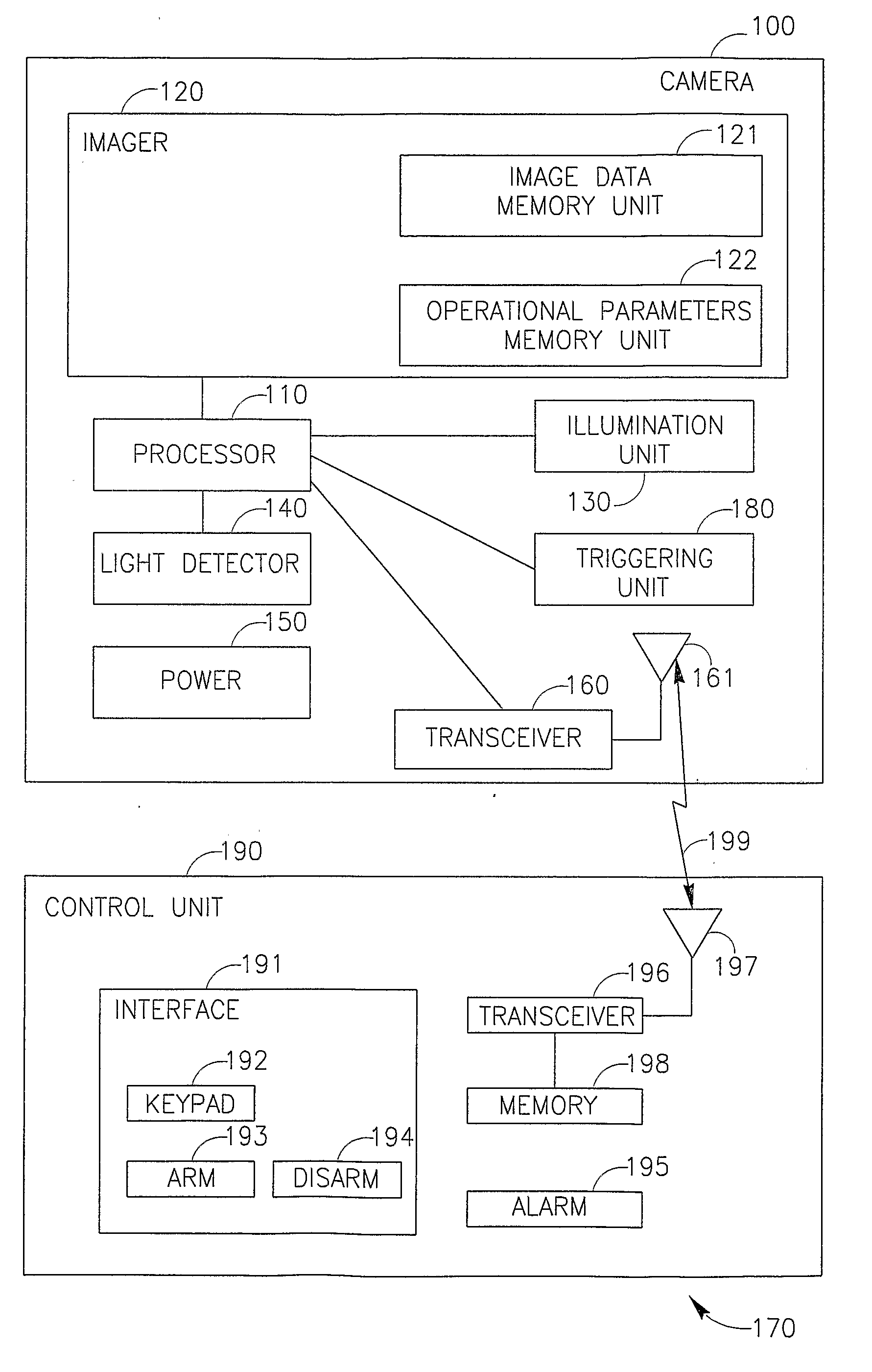
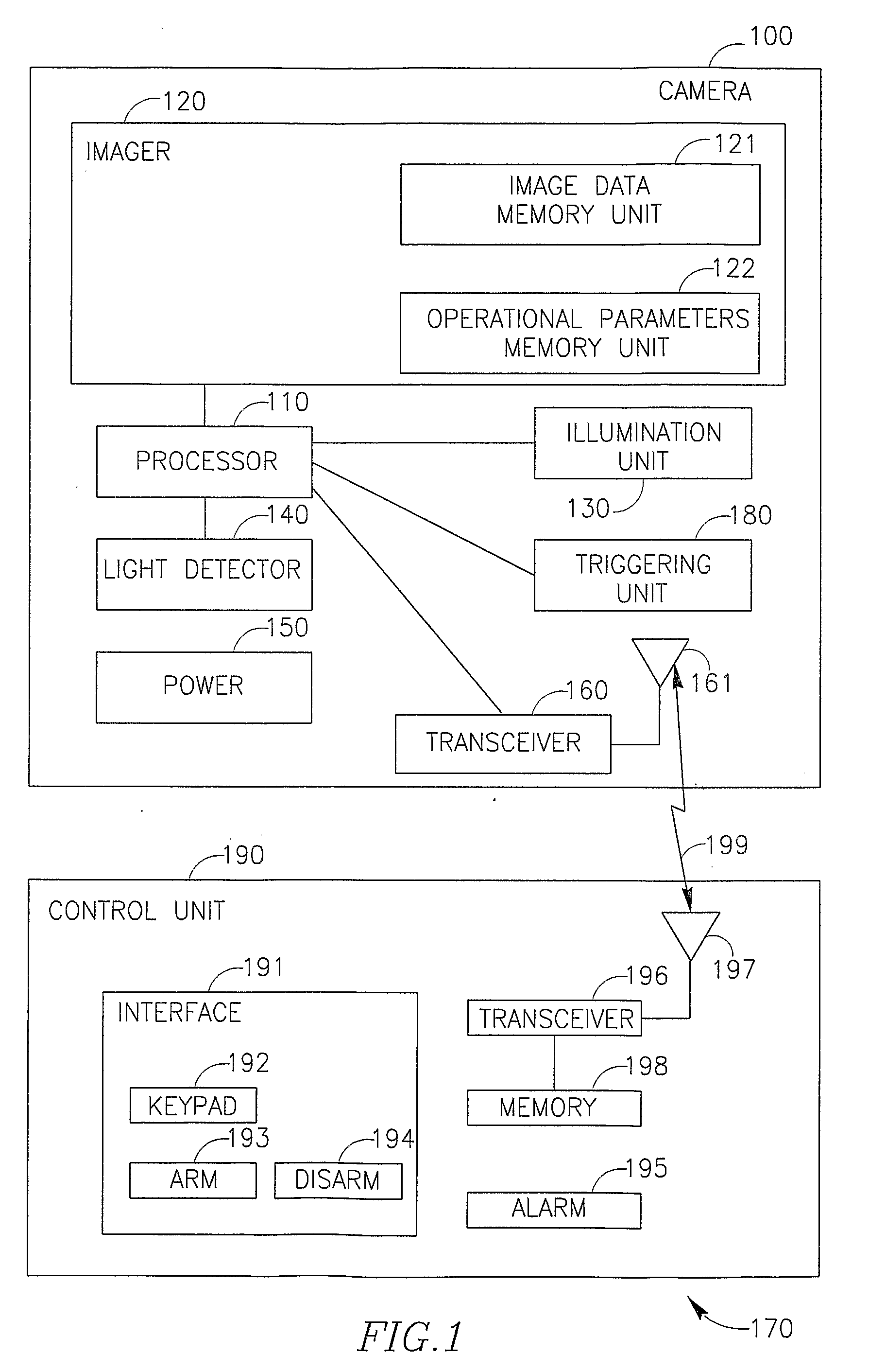
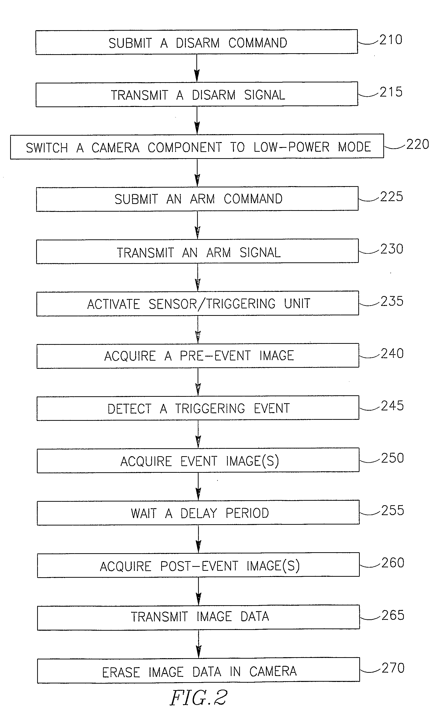
[0019]FIG. 1 schematically illustrates a block diagram of a low-power security / surveillance system 170 in accordance with some embodiments of the invention. System 170 may include, for example, a control unit 190 which may be operatively connected to one or more security cameras, e.g., camera 100.

[0020]Camera 100 may be or may include, for example, a non-mobile camera, a Pan Tilt Zoom (PTZ) camera, a surveillance camera, a traffic camera, a digital camera, or other suitable image acquisition unit. Camera 100 may includ...


PUM


Abstract

Devices, systems and methods of reduced-power imaging. For example, a device includes: an imager able to acquire one or more images; a triggering sensor able to sense a triggering event; and a receiver able to receive signals, wherein while the device is in a disarm mode the receiver is operational and the imager and the triggering sensor are not operational.

Description

FIELD OF THE INVENTION[0001]The present invention relates to the field of imaging and image acquisition, and, more particularly, to the field of imaging by security cameras and surveillance systems.BACKGROUND OF THE INVENTION[0002]Some security and surveillance cameras may include, for example, an imager (e.g., a Complementary Metal Oxide Semiconductor (CMOS) imager or a Charge Coupled Device (CCD) imager) which may be continuously operational and may constantly image a monitored area, thereby continuously consuming power. This may result in, for example, inefficient consumption of power, and may require the use of an external power source to constantly provide power to the imager.SUMMARY OF THE INVENTION[0003]Various embodiments of the invention provide, for example, devices, systems and methods for reduced-power imaging.[0004]Some embodiments include, for example, a security or surveillance system including a camera operatively connected to a control unit, e.g., through a two-way ...

Claims


Application Information

Patent Timeline
IPC IPC(8): H04N7/18H04N5/232
CPCH04N5/23203H04N5/23241H04N23/66H04N23/661H04N23/651
Inventor BENTKOVSKI, YAKOV
Owner PIMA ELECTRONICS SYST
Why Eureka
Try Eureka