

Reliability in a maskless lithography system
- Summary
- Abstract
- Description
- Claims
- Application Information
AI Technical Summary
Benefits of technology
Problems solved by technology
Method used
Image

Examples
Embodiment Construction
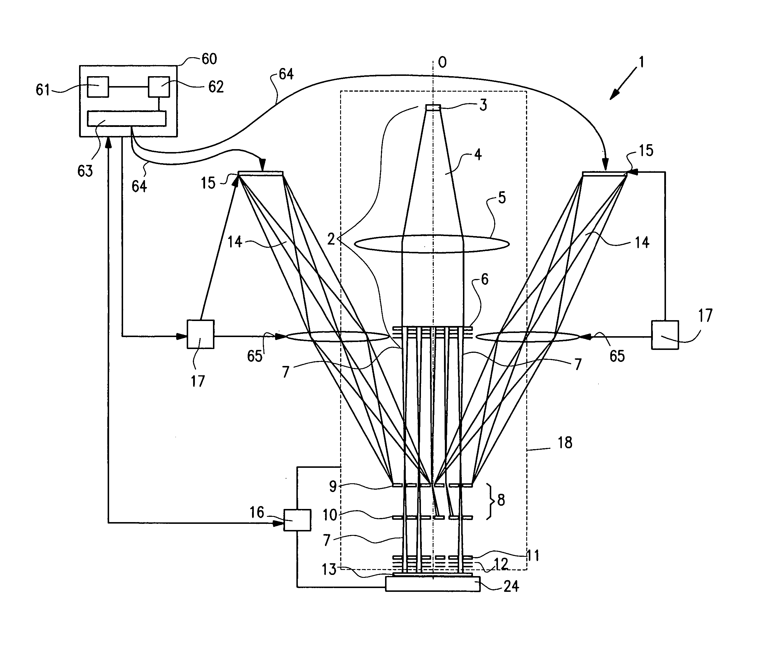
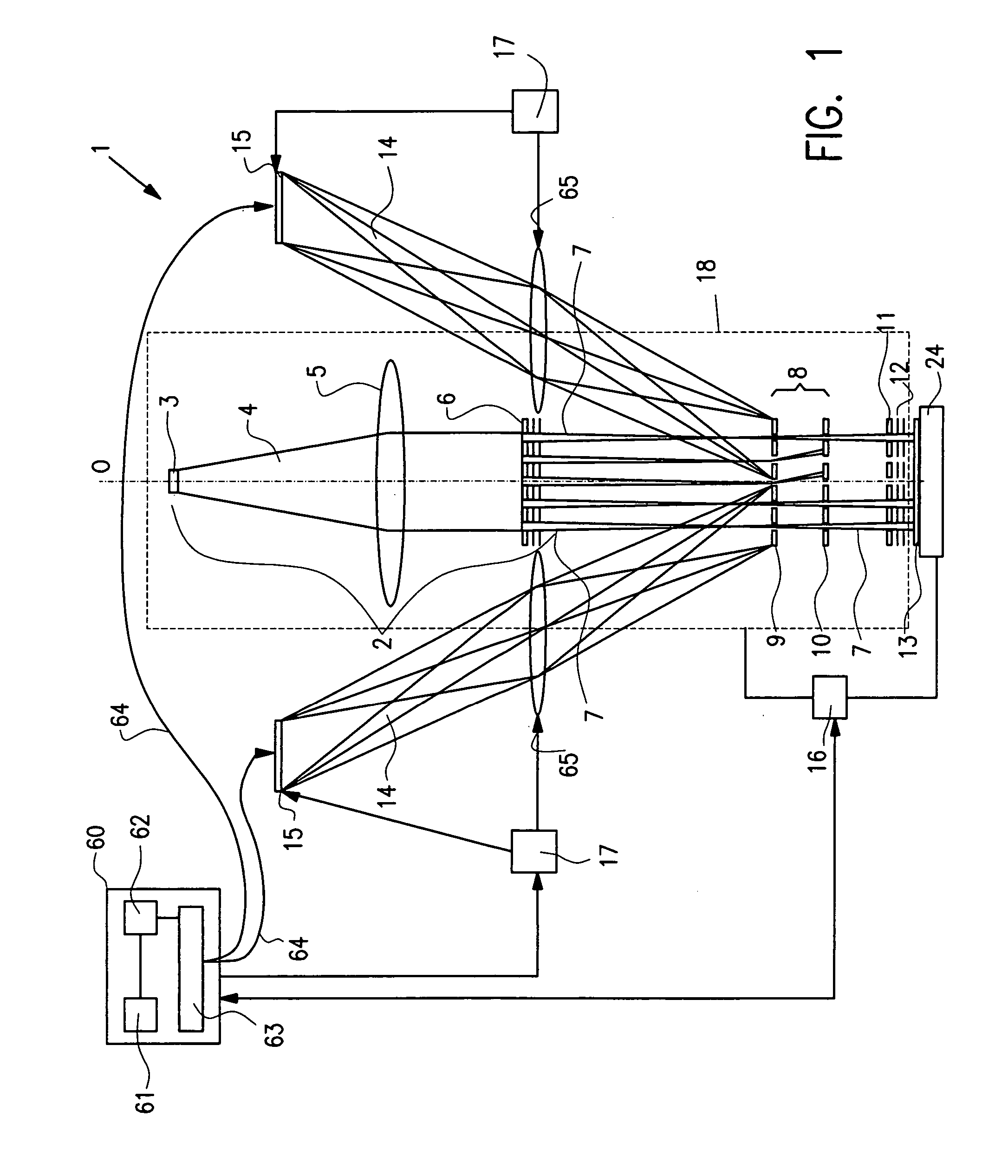
[0087] In FIG. 1, an overall side view is shown of a lithography system that can be used in the current invention.
[0088] The lithography system 1 comprises an electron optical unit 18, indicated with the stripped line, comprising a beamlet generator 2 with a source 3 generating a beam 4, a collimating optical system, represented by lens 5, for collimating beam 4, and beam splitter 6 for splitting the beam into a plurality of beamlets 7.
[0089] The resulting plurality of substantially parallel beamlets 7 is directed to modulator unit 8, that comprises an array of deflectors 9 and a beamlet stop array 10 for stopping each deflected beamlet.
[0090] Using electrostatic deflectors in the modulator unit 8, beamlets 7 are deflected away from the optical axis 0 of the system and beamlets 7′ pass the modulator arrays undeflected.
[0091] The beamlets 7′ passing stop array 10 are deflected at deflector array 11 in a first writing direction (scan direction) and the cross section of each beamle...
PUM
 Abstract
Description
Claims
Application Information