Anti-reflection device for an injection valve and injection valve

An anti-reflection and injection valve technology, used in fuel injection devices, special fuel injection devices, charging systems, etc., can solve problems such as pressure pulsation and fuel volume cannot be properly controlled, and achieve the effect of low hydraulic resistance

Active Publication Date: 2019-07-09
VTESCO TECH GMBH
View PDF7 Cites 0 Cited by
  • Summary
  • Abstract
  • Description
  • Claims
  • Application Information

AI Technical Summary

Problems solved by technology

A typical problem with such injection valves, especially high pressure valves, is the generation of pressure waves or pressure pulsations caused by injection events
Especially for multiple injection applications, internal pressure pulsations can cause problems because when the pressure conditions inside the injector are unstable or unknown when the valve is open, the amount of fuel injected cannot be properly controlled

Method used


Image

  • Anti-reflection device for an injection valve and injection valve
  • Anti-reflection device for an injection valve and injection valve
  • Anti-reflection device for an injection valve and injection valve

Examples


Embodiment Construction

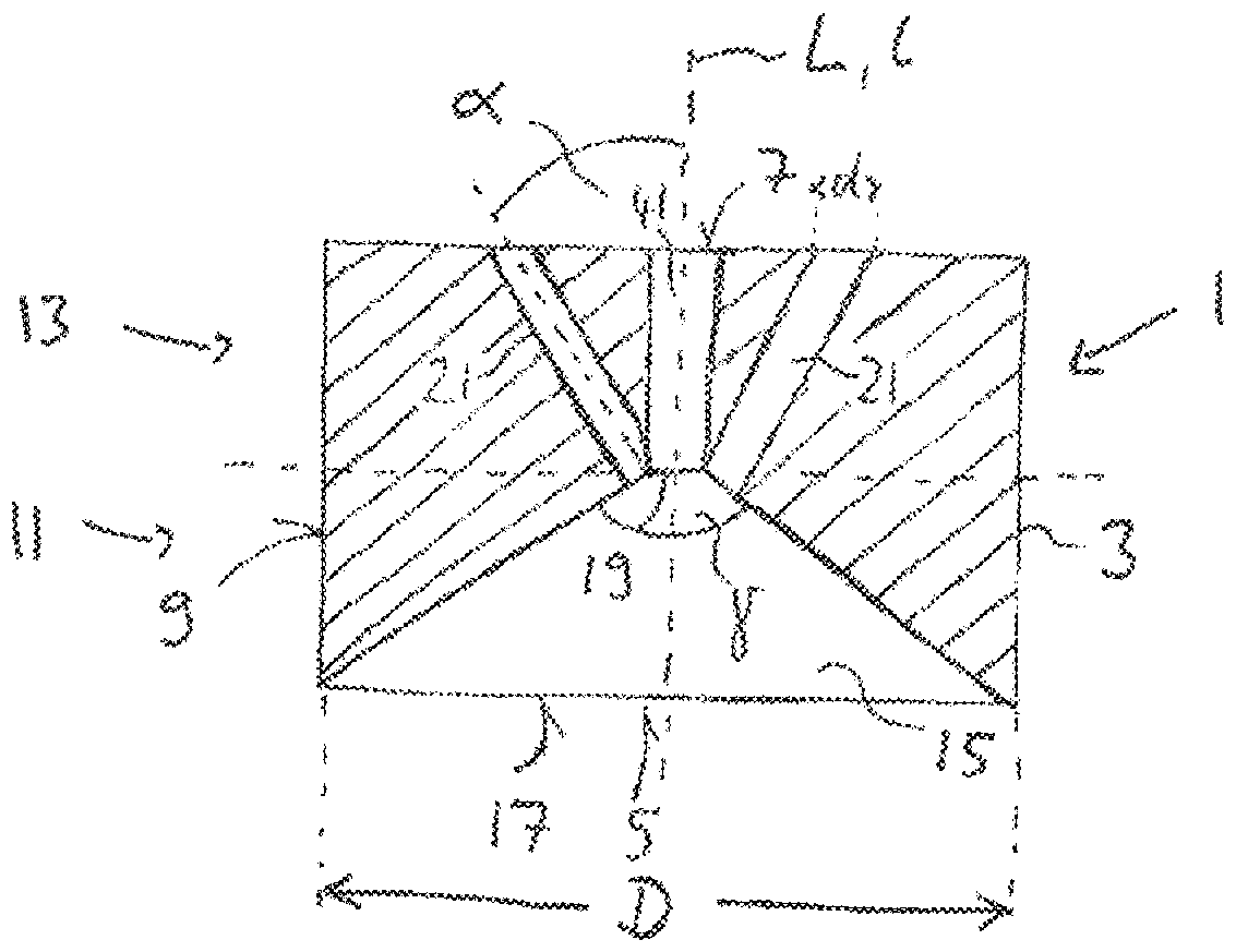
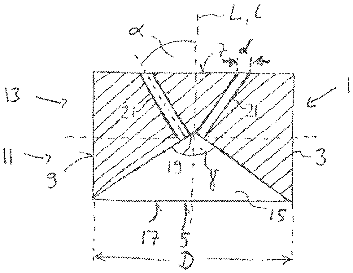
[0030] according to figure 1 The antireflection device 1 has a cylindrical base body 3 with a first base side 5 , a second base side 7 and a peripheral outer surface 9 . The longitudinal axis of the device 1 is denoted L.

[0031] The device 1 comprises two sections, a first section 11 and a second section 13 . The first section 11 extends from the first base side 5 to the central region of the base body 3 . The second section 13 extends from the second base side 7 to the central region of the base body 3 . The first section 11 and the second section 13 can overlap in the central region of the base body 3 .

[0032] Each section provides a hydraulic passage for fluid to flow through the device 1 .

[0033] The first section 11 comprises a chamber in the shape of a hollow cone 15 . The cone 15 has a base side 17 that is coplanar with the first base side 5 and is also part of the first base side 15 . In this embodiment, the longitudinal axis 1 of the cone 15 is identical t...


PUM


Abstract

An anti-reflection device (1) for preventing the reflection of pressure waves inside an injection valve (23), comprises a base body (3) with a first base side (5), a second base side (7) and an outersurface (9) and a longitudinal axis L to be orientated parallel to a propagation direction of a pressure wave. A first section (11) of the device (1) adjacent to the first base side (5) has a cavity being shaped as a hollow cone (15) and a second section (13) of the device (1) adjacent to the second base side (7) comprises at least one through-hole (21), the at least one through-hole (21) being influid communication with the cone (15). The at least one through-hole (21) and the hollow cone (15) hydraulically link the second base side (7) with the first base side (5).

Description

technical field [0001] The invention relates to an anti-reflection device for preventing reflections of pressure waves in an injection valve, and to an injection valve having such an anti-reflection device. Background technique [0002] An injection valve for direct or indirect injection of fuel into a combustion chamber of a vehicle is disclosed in document EP 2333297 B1. A typical problem with such injection valves, especially high-pressure valves, is the generation of pressure waves or pressure pulsations caused by injection events. Especially for multiple injection applications, internal pressure pulsations can cause problems because when the pressure conditions inside the injector are unstable or unknown when the valve is open, the amount of fuel injected cannot be properly controlled. Contents of the invention [0003] The object of the present invention is to provide a device which helps to solve the above-mentioned problems. Furthermore, it is an object of the in...

Claims


Application Information

Patent Timeline
Patent Type & Authority Applications(China)
IPC IPC(8): F02M55/04
CPCF02M55/04F02M2200/315F02M63/0036
Inventor M.格兰迪S.菲利皮W.许尔茨
Owner VTESCO TECH GMBH
Why Eureka
Try Eureka