Base for a high-pressure discharge lamp, and high-pressure discharge lamp

A high-pressure discharge lamp and lamp holder technology, applied in the use of gas discharge lamps, discharge lamps, transformer/inductor components, etc., can solve problems such as wall deformation and achieve the effect of saving fillers

Inactive Publication Date: 2011-07-13
PATENT TREUHAND GESELLSCHAFT FUR ELECTRIC GLUEHLAMPEN MBH
View PDF1 Cites 0 Cited by
  • Summary
  • Abstract
  • Description
  • Claims
  • Application Information

AI Technical Summary

Problems solved by technology

[0003] It has been found that in this lampholder due to the shrinkage of the material during hardening of the filling and the high forces acting on the wall of the chamber due to temperature changes, which lead to a considerable deformation of the wall, it is no longer possible to guarantee the maintenance of the plastic material. Dimensions of the finished lamp holder part

Method used


Image

  • Base for a high-pressure discharge lamp, and high-pressure discharge lamp
  • Base for a high-pressure discharge lamp, and high-pressure discharge lamp
  • Base for a high-pressure discharge lamp, and high-pressure discharge lamp

Examples


Embodiment Construction

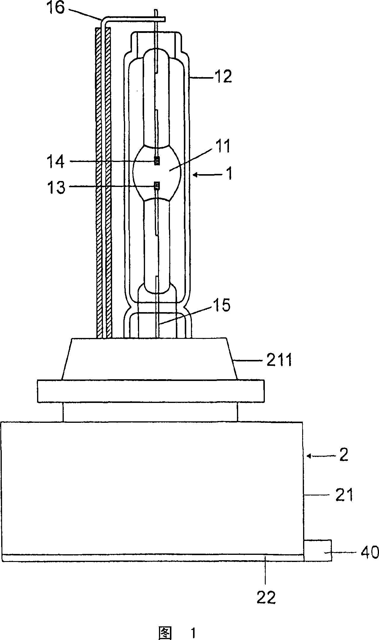
[0017] exist figure 1 In the preferred embodiment of the invention shown in , it concerns a single-sided socket-mounted high-pressure discharge lamp for a motor vehicle headlight. The high-pressure discharge lamp has a discharge vessel 11 enclosed by a glass outer tube 12 , which is made of quartz glass and in which electrodes 13 , 14 are arranged for generating a gas discharge. The electrodes 13, 14 are each connected to a supply lead 15 and 16 leading out of the discharge vessel 11, via which the electrodes are supplied with electricity. The structural unit 1 consisting of the discharge vessel 11 and the outer tube 12 is fastened in a seat 211 of the lampholder 2 . The lampholder 2 has a substantially cuboidal lower part 21 in which the electrical components for the ignition of the high-pressure discharge lamp are accommodated and which is equipped with a connection 40 for the high-pressure discharge lamp.

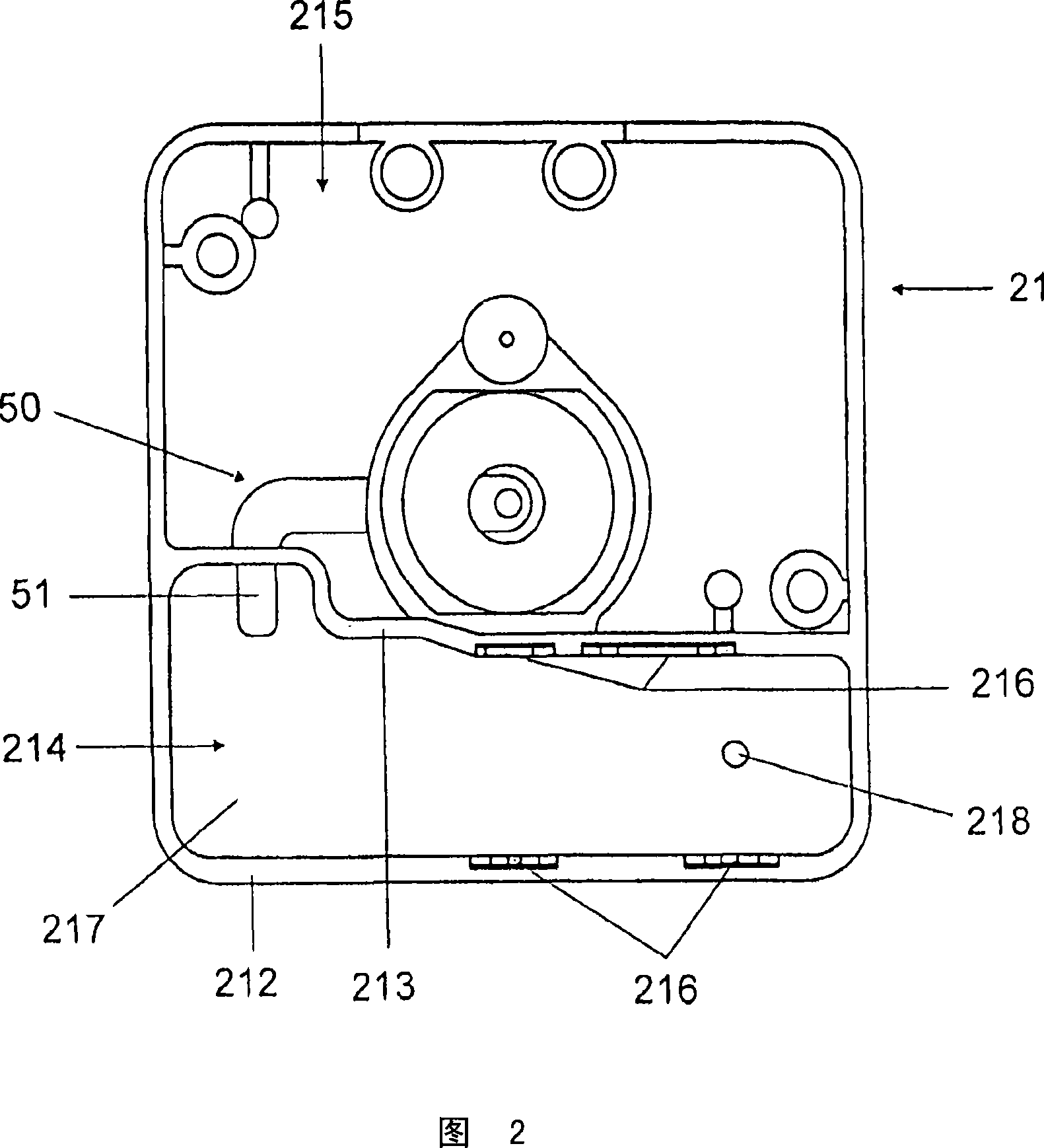
[0018] figure 2 A top view of the side of the lower part 21 fac...


PUM


Abstract

The invention relates to a base for a high-pressure discharge lamp comprising a transformer (300) that is disposed in a chamber (214) of the base (2). Sealing compound (6) is arranged in the interstice between the transformer (300) and the walls of said chamber (214). The terminal (301) of the secondary winding of the transformer (300), which is designed for high voltages, is embedded in the sealing compound (6). According to the invention, only some of the interstice is filled with the sealing compound (6).

Description

technical field [0001] The invention relates to a lampholder for a high-pressure discharge lamp and to a high-pressure discharge lamp comprising such a lampholder. Background technique [0002] Such a lampholder is known, for example, from EP1511130A1. This document describes a high-pressure discharge lamp for a motor vehicle headlight, which has a lamp base, in which a transformer is arranged, which is formed as a component of an igniter of the high-pressure discharge lamp. The transformer is located in a chamber of the lampholder, wherein the gap between the transformer and the wall of the chamber is completely filled with a filling and the high-voltage connections of the secondary winding are embedded in the filling. [0003] It has been found that in this lampholder due to the shrinkage of the material during hardening of the filling and the high forces acting on the wall of the chamber due to temperature changes, which lead to a considerable deformation of the wall, it...

Claims


Application Information

Patent Timeline
Patent Type & Authority Patents(China)
IPC IPC(8): H01F27/02H01R33/945H01R31/06F21Y101/00
CPCH01R31/06H01F27/04H01F27/022Y02B20/19H05B41/02H05B41/042H01F38/10H01R33/945Y02B20/00
Inventor W·巴茨M·罗尔
Owner PATENT TREUHAND GESELLSCHAFT FUR ELECTRIC GLUEHLAMPEN MBH
Why Eureka
Try Eureka