
Elevator arrangement structure

A technology for arranging structures and elevators, applied to elevators, lifts, transportation and packaging in buildings, etc., can solve the problems of poor car braking comfort, reduced hoistway space utilization, and large wear of guide rails and guide shoes. , to achieve the effect of stable operation of the car, compact elevator layout, and easy maintenance.

Inactive Publication Date: 2015-12-23
三六零安全科技股份有限公司
View PDF7 Cites 4 Cited by
  • Summary
  • Abstract
  • Description
  • Claims
  • Application Information

AI Technical Summary

Problems solved by technology

In the elevator layout structure currently on the market, the mainstream layout of the car guide rail and the counterweight guide rail and the existing defects are: 1. The vertical arrangement of the car guide rail and the counterweight guide rail will reduce the utilization rate of the hoistway space; 2. The car guide rail and the counterweight guide rail are arranged in parallel, but the line connecting the pair of car anti-rope pulleys on the car suspension with the traction rope is parallel to the center line of the pair of car guide rails. This is commonly known as backpack rack Although the utilization rate of the hoistway is high, due to the long distance between the suspension center and the center of gravity of the car, the guide shoes of the car are affected by the partial load, which leads to poor running and braking comfort of the car. And the guide shoe wears a lot, and frequent replacement requires a lot of cost

Method used


Image

  • Elevator arrangement structure
  • Elevator arrangement structure

Examples


Embodiment 1

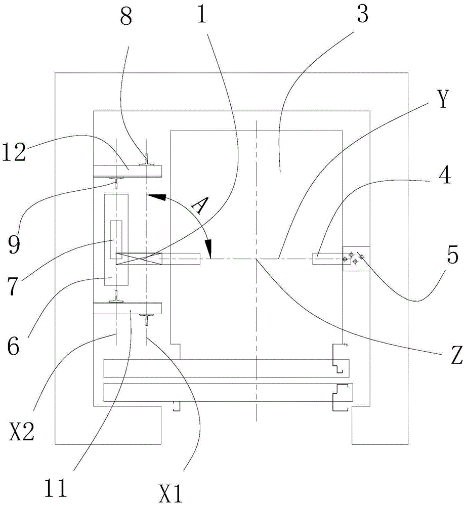
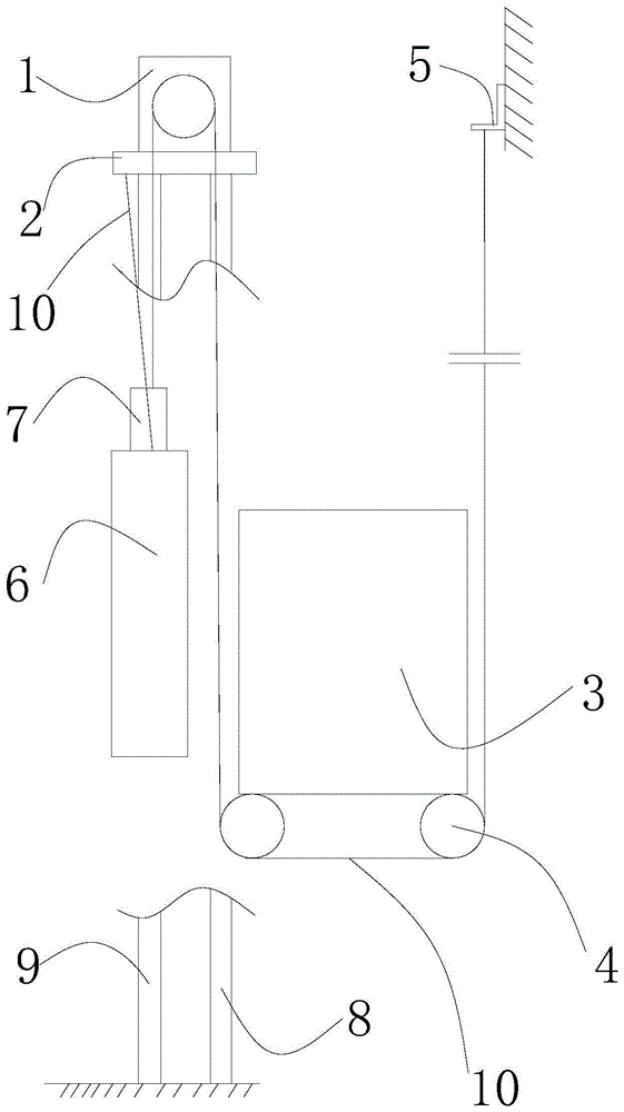
[0021] see figure 1 with 2 , an elevator layout structure, including a traction machine 1, a traction machine frame 2, a car 3, a pair of car anti-sheaves 4 respectively arranged on the left and right sides of the car 3, and a car side rope end fixing member 5. A counterweight 6 located on one side of the car 3 , a counterweight reversing sheave 7 arranged on the counterweight 6 , a pair of car guide rails 8 , a pair of counterweight guide rails 9 and a traction rope 10 . In this embodiment, a pair of car reversing sheave 4 is located at the bottom of the car 3 . In other embodiments, a pair of car reversing sheaves 4 can also be arranged on the top of the car 3 .

[0022] Wherein, a pair of car guide rails 8 and the pair of counterweight guide rails 9 are all located on the same side of the car 3, as figure 1 is the left side of car 3. The central line X1 of a pair of car guide rails 8 is parallel to the central line X2 of a pair of counterweight guide rails 9 . The trac...

Embodiment 2

[0027] The elevator arrangement structure of this embodiment is basically the same as that of Embodiment 1, the difference is that the acute angle A is 60°.


PUM

PropertyMeasurementUnit
Acute angleaaaaaaaaaa

Abstract

The invention discloses an elevator arrangement structure. The elevator arrangement structure comprises a traction machine (1), an elevator car (3), a pair of elevator car diversion sheaves (4), a counterweight (6), a counterweight diversion sheave (7), a pair of elevator car guide rails (8), a pair of counterweight guide rails (9) and a traction rope (10), wherein the elevator car diversion sheaves (4) are arranged on the left side and the right side of the elevator car (3) respectively. The pair of elevator car guide rails (8) and the pair of counterweight guide rails (9) are located on the same side of the elevator car (3). The center connecting line of the pair of elevator car guide rails (8) is parallel to the center connecting line of the pair of counterweight guide rails (9). The traction rope (10) intersects with the center connecting line of the pair of elevator car guide rails (8) on the extension line of the connecting line connecting the pair of elevator car diversion sheaves (4), so that an acute angle which is 60-90 degrees is formed. Compared with the prior art, the elevator arrangement structure is more compact, the utilization rate of the space of a shaft is increased, the elevator car operates more smoothly, and passengers can take the elevator car more comfortably.

Description

technical field [0001] The invention relates to an elevator layout structure, in particular to a machine room-less elevator layout structure with compact structure, more stable car running and higher hoistway space utilization. Background technique [0002] Due to the continuous improvement of the economic benefit requirements of modern buildings, how to arrange the cars of the same size in smaller shafts has become a research topic for elevator technicians. In the elevator layout structure currently on the market, the mainstream layout of the car guide rail and the counterweight guide rail and the existing defects are: 1. The vertical arrangement of the car guide rail and the counterweight guide rail will reduce the utilization rate of the hoistway space; 2. The car guide rail and the counterweight guide rail are arranged in parallel, but the line connecting the pair of car anti-rope pulleys on the car suspension with the traction rope is parallel to the center line of the ...

Claims


Application Information

Patent Timeline
IPC IPC(8): B66B9/00B66B7/02B66B11/04
Inventor 顾凯飞孙辰凯
Owner 三六零安全科技股份有限公司
Learn More