
Novel continuous beam type rail

A beam-type, new type of technology, applied in the direction of bridges, bridge materials, bridge construction, etc., can solve problems such as complex construction procedures, prone to falling beams, and prone to cracking, so as to ensure that the alignment is consistent with the design alignment, improve safety and Comfort and the effect of reducing the construction process

Active Publication Date: 2015-12-23
JIESHUN RAIL TRAFFIC TECH CHONGQING
View PDF7 Cites 10 Cited by
  • Summary
  • Abstract
  • Description
  • Claims
  • Application Information

AI Technical Summary

Problems solved by technology

[0004] 1. The construction and dismantling of temporary fixing brackets lead to complex construction procedures and reduce construction efficiency. Fixing track beams on temporary fixing brackets not only has a great impact on the municipal roads along the line, but also suffers from external interference, which is prone to beam falling incidents
[0005] 2. The construction needs to be carried out sequentially and in one direction. Due to the great influence of the joint project, the bridge erecting machine cannot be used to erect the beam. It is difficult to erect the beam in special areas (such as high slopes and valleys), and the construction period cannot be guaranteed.
[0006] 3. Secondary tensioning through long prestressed steel strands is likely to cause deformation of the track beam, and the deformation cannot be repaired, so the alignment of the completed bridge may be inconsistent with the design alignment, which will affect the safety and comfort of the later train operation
[0007] 4. Two side-span beam pier columns are used, which are respectively consolidated with each side-span track beam with cast-in-place concrete. Cracking occurs, affecting the durability of the structure

Method used


Image

  • Novel continuous beam type rail
  • Novel continuous beam type rail
  • Novel continuous beam type rail

Examples


Embodiment Construction

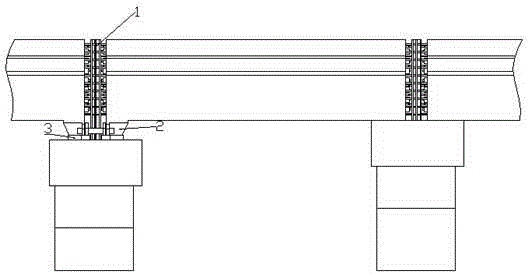
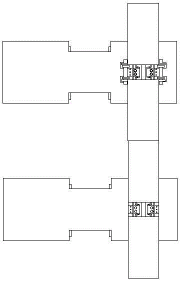
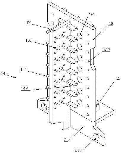
[0031] The present invention will be described in detail below in conjunction with accompanying drawing, as figure 1 Shown:

[0032] The novel continuous beam track of the present invention comprises a pier column and a track beam fixedly connected with the pier column, and a cover beam is poured on the upper part of the pier column, and a continuous beam includes two side span beams and two side span beams connected with the side span beams respectively. A mid-span beam, the two ends of the mid-span beam are pre-embedded with connecting members 1, and the connecting members 1 are used to connect adjacent track beams and consolidate the track beams on the cover beam; the two ends of the mid-span beam are pre-embedded with A connecting member 1, which is used to connect adjacent track beams and fix the track beams on the cover beam; one end of the side span beam is provided with a connecting member 1, and the connecting member 1 is used to connect adjacent The mid-span track b...


PUM


Abstract

The invention discloses a novel continuous beam type rail, and relates to the technical field of rail structures. The novel continuous beam type rail comprises a pier column, and a rail beam fixedly connected with the pier column, wherein a cover beam is cast at the upper part of the pier column; a continuous beam comprises two side span beams, and a middle span beam respectively connected with the side span beams; the two ends of the middle span beam are embedded with connecting components for connecting the cover beam with the adjacent rail beam; connecting components are arranged at one ends of the side span beams; brackets fixedly connected with the connecting components are arranged at the other ends of the side span beams; and a support device is arranged on the cover beam, and is connected with the brackets. The novel continuous beam type rail has the following beneficial effects: the rail beam is embedded with the connecting components, and the cover beam is embedded with the support device, so that the rail beam and the cover beam can be temporarily fixed, a temporary support system has no need to be built, the construction procedure is reduced, the construction cost is saved, and the construction efficiency is improved; and a bridge girder erection machine can provide convenience for the construction of special sections, so that the construction efficiency is improved.

Description

technical field [0001] The invention relates to the technical field of track structures, in particular to a novel continuous beam track. Background technique [0002] During the construction process of continuous track beams, 3~5 track beams are connected into one joint, the beams connected between one joint and another joint are side-span beams, and the beams located in the middle of the side-span beams are mid-span beams. During construction, the lower pier columns are usually poured first, and after the pier columns are poured, temporary fixing brackets are built on the cover beams to fix the track beams to facilitate the connection of the two track beams, and then the prefabricated track beams are hoisted to the cover beams , use temporary fixing facilities to fix the track beam, then bind the joint steel bars, run through the long steel strand, pour the intermediate joint concrete and maintain it for 15 days, carry out secondary tension and pull through the long prestre...

Claims


Application Information

Patent Timeline
IPC IPC(8): E01D2/00E01D19/00E01D101/28
Inventor 赵晓波吴焕君吴天陈波李艳青张富贵郭鸿飞周胜怡张炯王波涂海
Owner JIESHUN RAIL TRAFFIC TECH CHONGQING
Learn More